I wanted to make my home automation to be cheap. Commercial solutions, like KNX was a way too expensive for me; besides creating own system gives great benefits like better knowledge about how it works, possibility to customize it to my needs (including software) and of course much fun 🙂
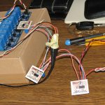
So I just bought some 5V 8-channel relay boards on the eBay. Because it has 8 channels to control, so I used a DS2408 8-channel, programmable I/O 1-Wire chip.
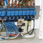
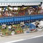
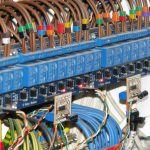
There was a kernel module for this chip (w1_ds2408). So the only thing left, was to design a small board for DS2408 which I could then connect to the 1-Wire bus:
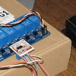
The Vcc and GND is connected on the right side of the relay board. Because my DS2408 board is powered from the same power source as the relay board, so the GND is common. At idle state there is a logical “1” on all inputs – all relays are “off”. To switch “on” the relay, the DS2408 just pulls selected input to GND.
Firstly I designed this board with the DS1811 power-on-reset circuit. It was working quite nice but only without load. When I was switching the relays with 230V of load, that was triggering the DS1811 power-on-reset chip and the DS2408 was resetting.
I removed that DS1811 and inserted a 10K resistor between Vcc and the RSTZ pin instead (I wanted all relays to be “off” after powering on). I also added a 47uF electrolytic capacitor near the power input to suppress the noise.
After that fixes, controlling the relays is now working stable 🙂
Every board has it’s unique address, so to control the relay board I just need to send a one-byte value to the module’s sysfs output file, for instance:
/sys/bus/w1/devices/29-0000001137c7/output
Every bit from that byte corresponds to specific relay of the relay board. Simple as that 🙂
Hi Manio,
Thanks a lot for your posts, it’s indeed helpful for people like me who wanna start a new project similar to yours.
I’ll give it a try with your solution about cheap 1wire module (ds2408).
May I ask you some questions ?
How did you do with interrupters (to turn on/off lights) ? Did you also use 1-wire to connect together all interrupters from all rooms ?
I’m also wandering about the length of the circuit… Does it work for a whole house ? Is it better to use different circuit ?
Wishing you all the best for your projects =)
Best regards,
Laurenzzo
Hi Laurenzzo,
Sure, answering your questions:
Yes, I am also using 1wire for all switches in all rooms. The difference is that a switch is connected to my small “sensor board” with DS2413 instead of high voltage. I am only constantly checking all switches state in a loop and detecting a changes. The change is triggering relay and respectively turning ON/OFF the associated light 🙂
But generally I am using switches very occasionally, because the lights are triggered from my PIR sensors (also connected to my “sensor boards”).
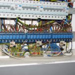
Yes, it is working for a whole house. As I described here:
https://skyboo.net/2017/02/raspberry-pi-1wire-bus-master/
I was tested it with 45.2m cable and 22 slave devices on single bus. I did not test it on a longer distance just because I didn’t have additional cable at the moment 🙂
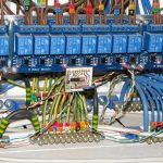
But in my house my buses are diverging from one central bus master place (RPi), so I have four 1wire buses for a ground floor. On all buses I also have a DS18B20s for temperature monitoring in every room.
It is all working very well for three-four years so far 🙂
I tried connect ds2408 to Raspberry , but without any success .
I already read maybe all google search but cant open “secret” of use this chip . Can you give circuit diagramm of your connections and detail sample as possibe change logic level on the pins od DS2408 .
Hi Vlad,
You did not provide basic information. First of all – is your DS2408 detected in linux filesystem? What you mean by “secret” use of this chip? 🙂
What device you want to drive using the chip? Also a relay board? If so, than in idle state there should be a +5V on the input pins and if you set the chip output bit to ‘0’ then the relay is switched “on”.
Hello Manio
About the –
when i connect ds2408 to Raspi , Linux found the chip and i seen ID , ican see the file system of internal registers .
but unfortunately when i tried change levels on pins , – nothing , i check the multimeter but nothing. Maybe you can based on your expirience explain to me how possible change level on pins.
Manio
I know this is an old post, but just wondering if you could offer some advice on using the DS2408.
I have it working on the OW my only issue is the “output” file is owned by root, and I have to use sudo for my app to write to it.
Besides the above or changing permissions on the file (which I think will get reset ) any suggestions?
Thanks,
j.
Hi. You did not mention anything about distro you are using, but mainly you could assume that you have to add your user to some specific group to be able to write to this file without sudo.
Sorry Manio
I am using Raspberry Pi Buster arm64 (I wanted to develop in swift). If I am reading the below correctly, only root has write permissions:
pi@raspberrypi:/sys/devices/w1_bus_master1/29-0000001d555a $
-rw-r–r– 1 root 1 Dec 9 08:06 activity
-r–r–r– 1 root 1 Dec 9 08:06 cond_search_mask
-r–r–r– 1 root 1 Dec 9 08:06 cond_search_polarity
-r–r–r– 1 root 4096 Dec 9 08:06 id
-r–r–r– 1 root 4096 Dec 9 08:06 name
-rw-r–r– 1 root 1 Dec 8 18:53 output
drwxr-xr-x 2 root 0 Dec 9 08:06 power/
-r–r–r– 1 root 1 Dec 8 16:12 state
-rw-r–r– 1 root 1 Dec 9 08:06 status_control
-rw-r–r– 1 root 4096 Dec 8 16:11 uevent
Also do you know if there is any documentation on the above files? I am using ‘output’ to set the relay’s & and reading ‘state’ to check state, just wondering of any of the others provide additional info/functionality
No, a regular user can also read the file if it has been assigned to desired system group.
A standard set of files are provided for regular slave devices. Additional files are a matter of specified driver.
Documentation is here: https://github.com/torvalds/linux/tree/master/Documentation/w1/slaves
Hi, I’m also struggling to make DS2408 work with Pi 4 – so far no luck. Ds2408 has external 5V power supply. I have connected GPIO 4 to I/O and added 4.7k resistor between GPIO4 and 3V3 and connected the ground. Raspian is detecting my device and I can read from it, however when I try to write something using:
echo -e ‘\x02’ > /sys/bus/w1/devices/29-000000115b0b/output
i get Input\output error. I have tried various commands and connections with/without pullups and I just can’t make it work… 🙁
I would really appreciate your help, this is my collage final project.
PM me serus1604@gmail.com
It is not so bad if your Pi is detecting the device and you can read the state. Are you trying to write as the root user?
Yes, writing as normal user gives permission denied. What’s interesting, hexdump of state and output differs. Shoulnd’t they be consistent?
Ok, never mind – I found what was causing troubles – it started working when I added 10k resistor between RSTZ and Vcc. Additionally I had to use echo -n -e ‘\x02’ > output to avoid file too large error. By the way I changed my OS to ubuntu but idk if it had any impact.