TL;DR #
This lengthy post is about designing and deploying my new ESP32 rust project (for the first time in my life) and all its struggles. It is using the ultrasonic sensor for liquid level monitoring.
History (previous setup) #
Long story short my house still cannot be connected to the sewerage system, so I had to use dedicated tank (cesspool) for domestic sewage.
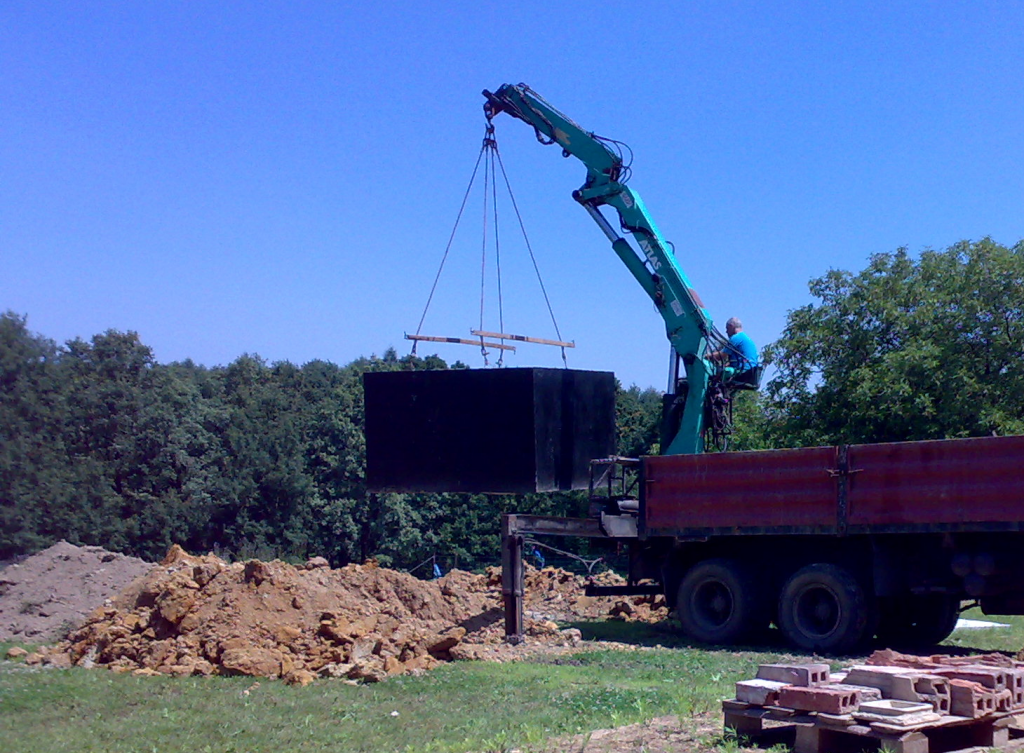
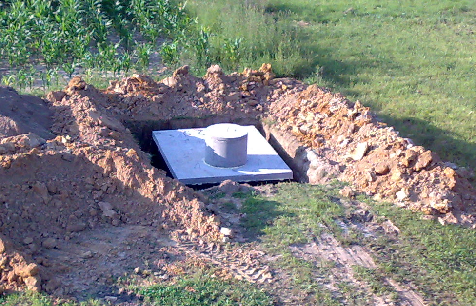
Of course, I would like to know what is the liquid level inside. Because all my house is wired with 1-wire so my first approach was to just add three float switches-based sensors on different levels (low/medium/high) inside the tank:
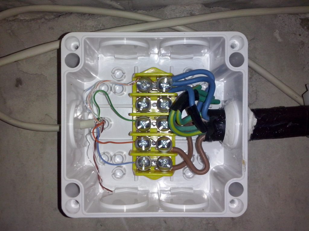
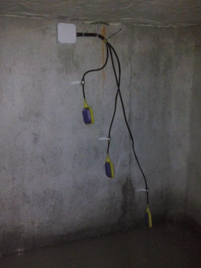
This setup was working for about seven years. The general setup was OK but there was one design problem: I’ve put the junction box inside the tank. During that time I had one problem: the liquid gets into the junction box, because (despite my efforts), it was not properly sealed. Even when the cesspool was finally pumped out, I still had incorrect reading (as sensors were active).
Finally, because I cannot get inside the junction box again (corroded screws), I’ve drilled a small hole on the bottom of the box and the water leaks out. But the problem has started since then: over next years the reading was sometimes troublesome. The levels was flip-flopping in some specific circumstances (especially when there was high humidity weather conditions). And because the junction box was inside and without easy access, I realized that I need to build something better…
The plan #
I know that the environment inside the tank is harsh, and I also wanted to have something better, with much better accuracy. I knew some ultrasonic sensors for Arduino (like HC-SR04):
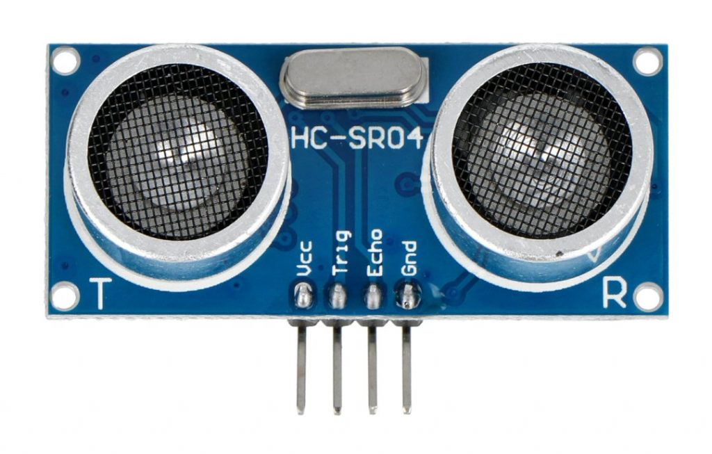
… but it was too big and cannot be placed inside. During my research I found some nice project by Pablo Cruz Lemini: https://pablocruz.io/water-level-monitor/
The sensor was waterproof and only the sensor was inside, and the electronics could be outside. This is what I wanted :)
Finally, I ordered the ESP32 (for the first time ever) and JSN-SR04T (main board + one sensor).
Research #
Regarding the software/examples, I was inspired mainly by those three projects:
- https://github.com/martinius96/hladinomer-studna-scripty
- https://github.com/pantaluna/esp32_jsnsr04t_using_lib
- https://github.com/portfedh/WaterLevelSensorMQTT
Here I want to thank all the authors for inspiration and sharing hardware schematics and the code :)
Regarding the firmware: recently I am a Rust fan, so if there would be some possibility to write the software in Rust, it would be a huge benefit for me. I hoped that migrating the C code to Rust should be possible. I started googling and it seems that there is some Rust community around Espressif chips: https://github.com/esp-rs
I could choose an IDF-based HAL with Rust std support, or some more bare-metal no_std, called esp-hal.
Firstly, I was planning battery-based system but after contacting Pablo ( pablocruz.io) I changed my mind and decided that I will power the ESP from the regular power adapter. Regarding communication, I decided that WiFi will be just fine, and also found a esp-wifi project for this.
Overall, the Espressif-Rust community is great and really helpful. For the start I recommend this clip:
Development and desktop testing #
Unfortunately (as I supposed) the start was not really easy. All problems are now solved but this is a quick recap of problems I encountered during this phase:
First of all I had a problems with programming the ESP32 under Linux using the dedicated espflash utility: https://github.com/esp-rs/espflash/issues/394#issuecomment-1646554985. I had to use patched version which includes PR#387. Finally, this problem was fixed (at the end of my developing phase).
This way I was able to make and run a ‘Hello world’ app. Next I added a WiFi support; a bjoernQ’s Demo of Rust on ESP32 (no RTOS) with MQTT and adafruit.io for temperature logging was also helpful.
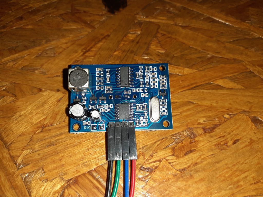
Regarding the hardware and wiring: I have version 3 of the JSN-SR04T module with dedicated main board and external sensor:
1. The Rev 3.0 as we have here and older Rev 2.0 of this module are stated to be 3.3V compatible as well as 5V. We have found 3.3V operation to be spotty at best in our testing, so if using with a 3.3V MCU, it is recommended to operate the module at 5V and use level shifting for the logic lines going to the MCU.
https://protosupplies.com/product/jsn-sr04t-v3-0-waterproof-ultrasonic-range-finder/
Ultrasonic sensor is powered from 5V, while the ESP32 data pins designed for 3.3V. So I needed to add a voltage divider. I looked at several schematics and I ended up with similar wiring as here: https://apollolabsblog.hashnode.dev/esp32-embedded-rust-at-the-hal-timer-ultrasonic-distance-measurement
I contacted the author because initially he also doesn’t place the divider there, but now the schematic is updated.
Then I wired up the ultrasonic sensor on a beagle board and started to measuring the time frames which are needed to correctly compute distance. First I was doing the measurement in single thread, it was working fine, but I knew that when I add other tasks (eg. WiFi support) then the async/await would be a good solution for this. An embassy project comes with help, besides, I could use calculation based on intervals: eg. waiting for a rising/falling edge of a pin in an async task.
This is the function I was using at a time for measuring the distance:
When I added all the WiFi stack (and also raised the clock to 240MHz, which is required) the whole ESP becomes really unstable. It was working for several minutes max. Moreover, the async code which I was using messed a little with the timings and distance calculation, so it is has visible drift.
I reported this problem in esp-wifi#226
Fortunately the sensor has several working modes. I was using the default one, in short: I was starting the process using the TRIGGER pin and calculating how long the ECHO pin is up. The distance is then calculated using specified formula (look above in the sample code), so this time was crucial - as this directly influences the calculated distance. And this was not as reliable as before (when only this single task was running on the ESP).
I’ve got this readings:
Distance = 47.2cm Distance = 47.3cm Distance = 47.2cm Distance = 47.2cm Distance = 47.4cm Distance = 50.8cm Distance = 47.2cm Distance = 47.3cm Distance = 47.2cm Distance = 47.5cm
Sometimes it was differing even some centimeters (sic!) while I didn’t touch the sensor at all.
Fortunately the AJ-SR04M module I am using has other working modes. It can eg. send UART data like a serial device using the same ECHO pin. I started considering to testing other working modes.
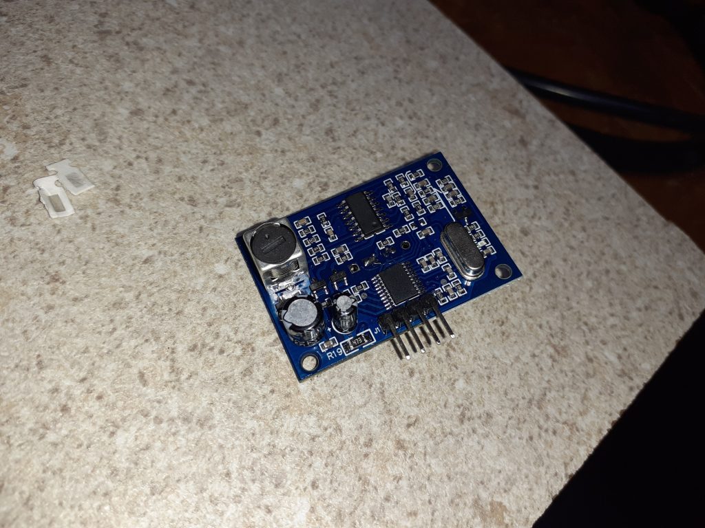
It can work with 5 modes. Default is 0 - this is the trigger and echo. Modes can be changed by changing the R19 resistor value. By default on R19 there are empty pads (open):
I also read, that sometimes, the firmware is not able to change modes (or not all modes are available) so to make first test I shorted the resistor pads (0 Ohms).
This way I changed the mode to Mode 5 which is really nice because the ultrasonic sensor is doing the whole measurement itself (which is perfect every time) and it is sending the final value to ESP. I was not sure whether this will work, but… finally I’ve got this:
Gap=478mm Gap=478mm Gap=478mm Gap=478mm Gap=478mm Gap=478mm Gap=478mm Gap=478mm Gap=478mm Gap=478mm Gap=478mm Gap=478mm Gap=478mm Gap=478mm Gap=478mm Gap=478mm Gap=478mm
…. and still the same value when I don’t touch the probe! :)
I don’t need to say that I really like this approach, as it seems, that the measurement is really stable and done by the sensor itself, not in ESP which is vulnerable to some “time drifting”.
Mode 5 I was using is outputting an ASCII text: “Gap=…”. It was OK for testing but finally there is also Mode 4 which I preferred most, as this is a binary format and also a simple CRC byte is added.
I ordered some resistors pack including a 47k Ohm SMD resistor (as I don’t have that), to be able to enable Mode 4. Finally, I soldered it in place:
… and adapted the code for using the binary UART instead of ASCII.
Long-run testing #
In the meantime I was doing reliability tests and it turns out, that there are is some nasty bug. I opened a esp-hal discussion#762 asking about it.
The problem appears after longer time period, eg. after several days of work.
The internal ESP buffer pointer was bad at some point, so I was trying to figure out why…
After a weeks of testing (including oscilloscope testing to be sure that there are valid data on the wire) and thanks to Björn Quentin’s help, I was finally able to make a patch for this problem.
Moving to “production” environment ;) #
I enabled the internal watchdog timer in the code and decided that this is the time to test it in target location :)
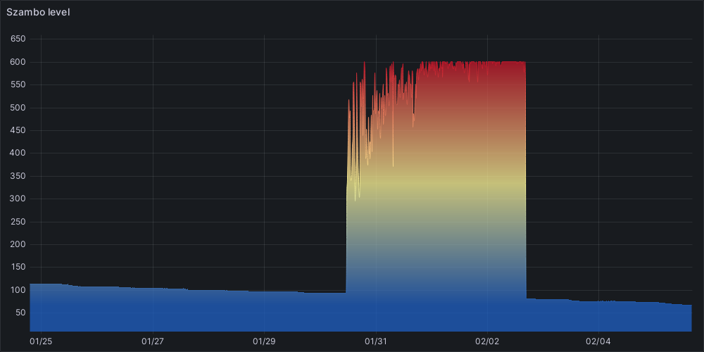
First I had the sensor on top but floating on wire - as you can see the graph was drifting from 79 to 58cm:
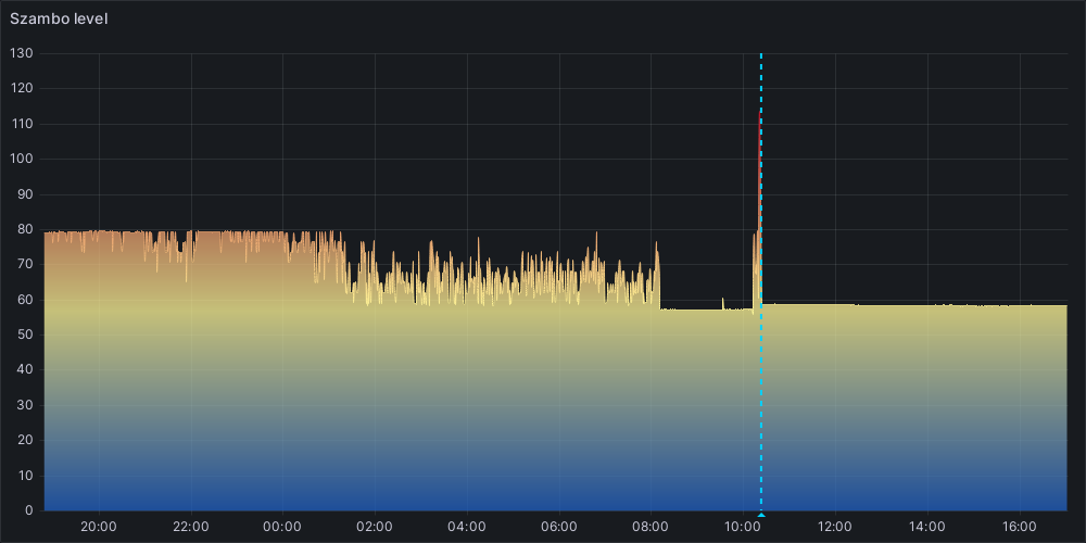
Next day I glued it there with a silicone, and I was thinking that it is working better (after the vertical blue dotted-line on the above graph).
But at the end of the day I realized that I constantly have about 58cm!
I was filling the tank the whole day so this was impossible!
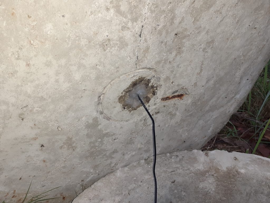
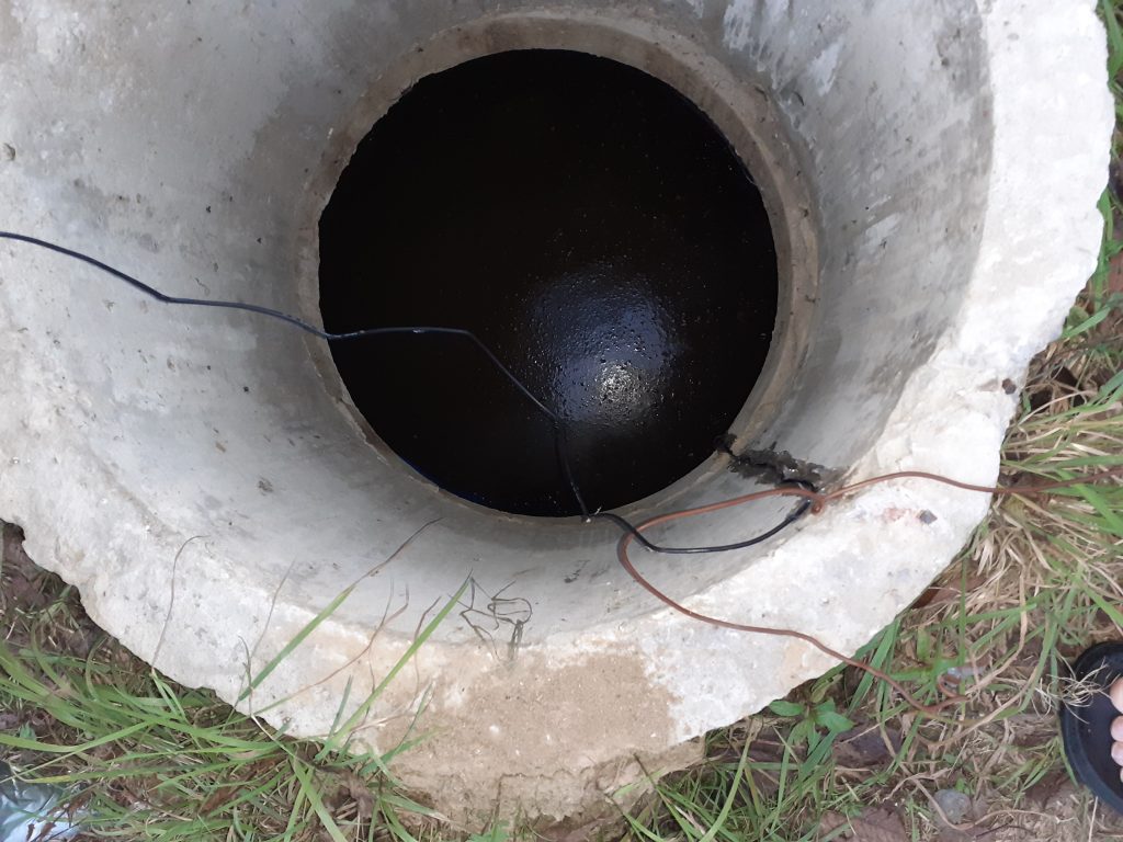
I went there and measured the distance to the liquid. I realized that it was measuring the initial distance (look below) only!
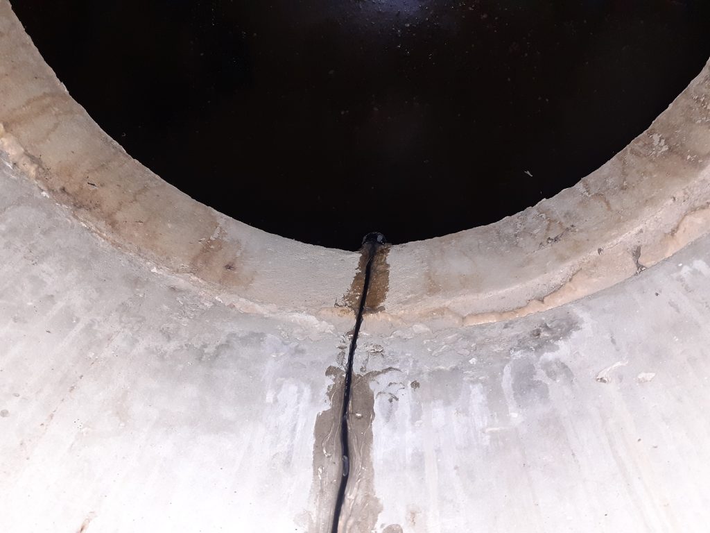
As the last resort I moved the sensor much more down just above the liquid (without any obstacles in-between). The sketch (sorry for the quality) is showing this:
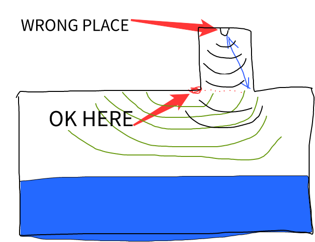
This leads to more realistic data and this distance graph:
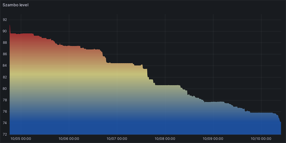
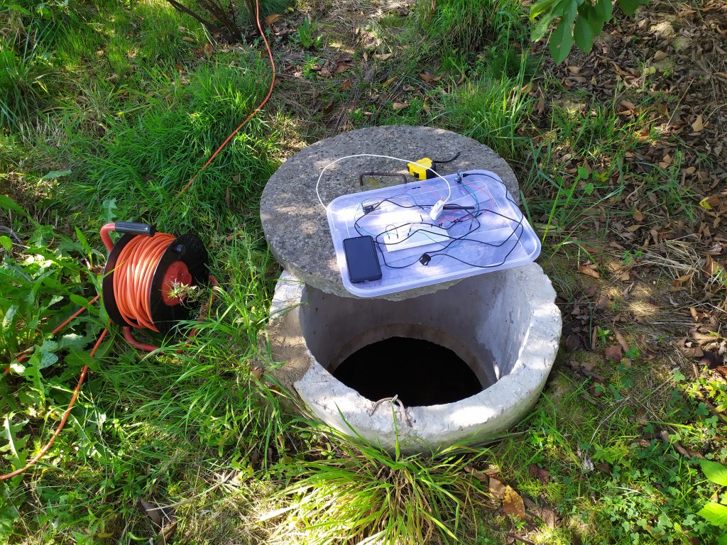
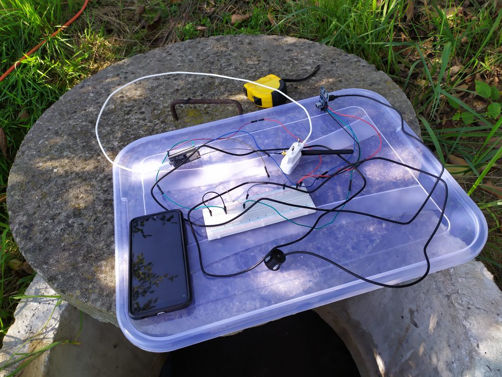
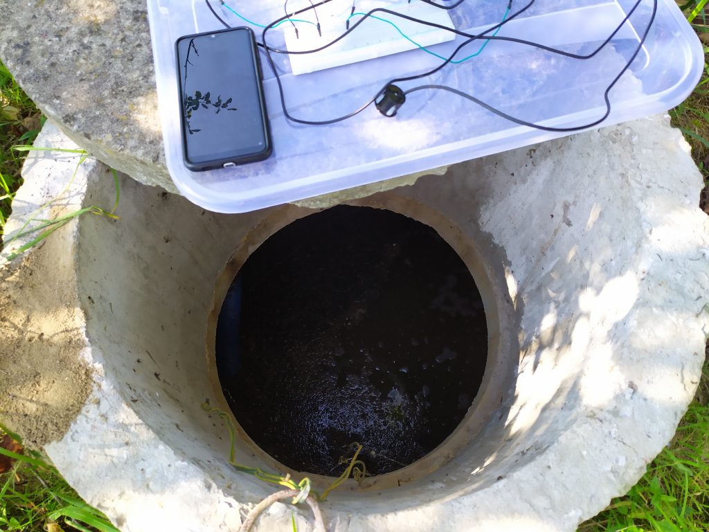
And now some more recent photos how it looks:
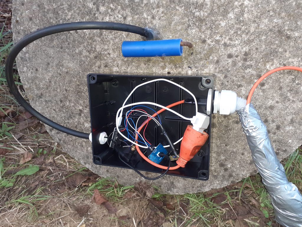
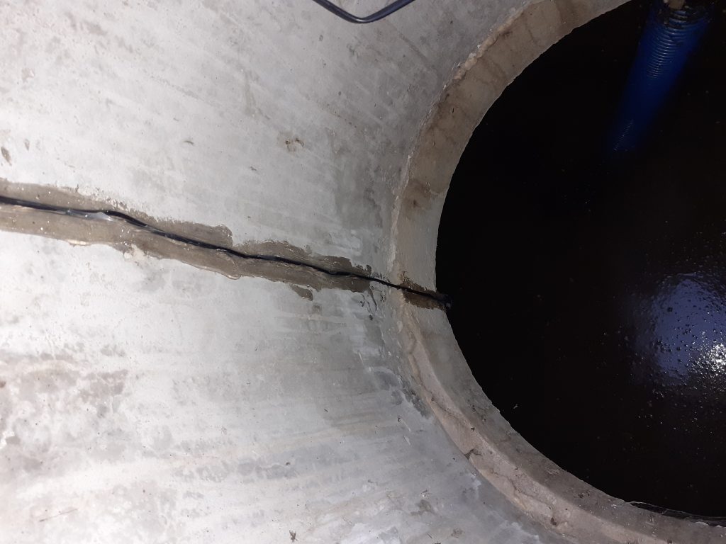
Final #
The hardware part is almost done for me (I only need to properly run the power cable, as you can see on the above photos, this is currently temporary solution).
I will try to share the final source code on my github, but first I need to clean it up, as it is currently with a lot of commented/disabled stuff, etc.
It is now working for several months and the software part is really reliable (I am also monitoring ESP uptime). Nevertheless, during that time I had two outages. The problem seems the same in both cases:
Under some environmental/weather circumstances (probably related to dew point) the water is condensing on the top/ceiling of the tank like here:
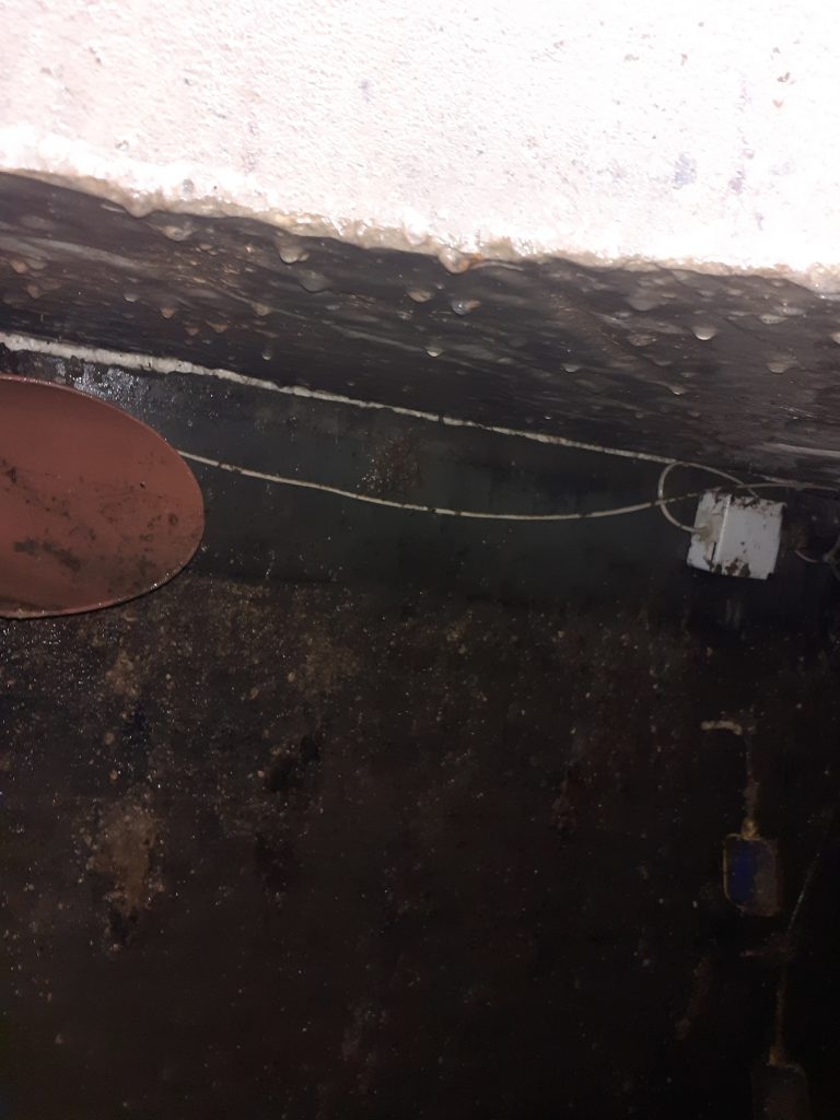
… thus also the sensor gets wet. This is leading to this on the graph:
The solution is: open the cover and manually wipe off the drops from the sensor, then it is working back again. Unfortunately I didn’t find better solution for this. I only hope that this will be rare problem.
That’s all, thank your for your time :)