Raspberry Pi 1-Wire tests, DS2482-800

Bit bangling

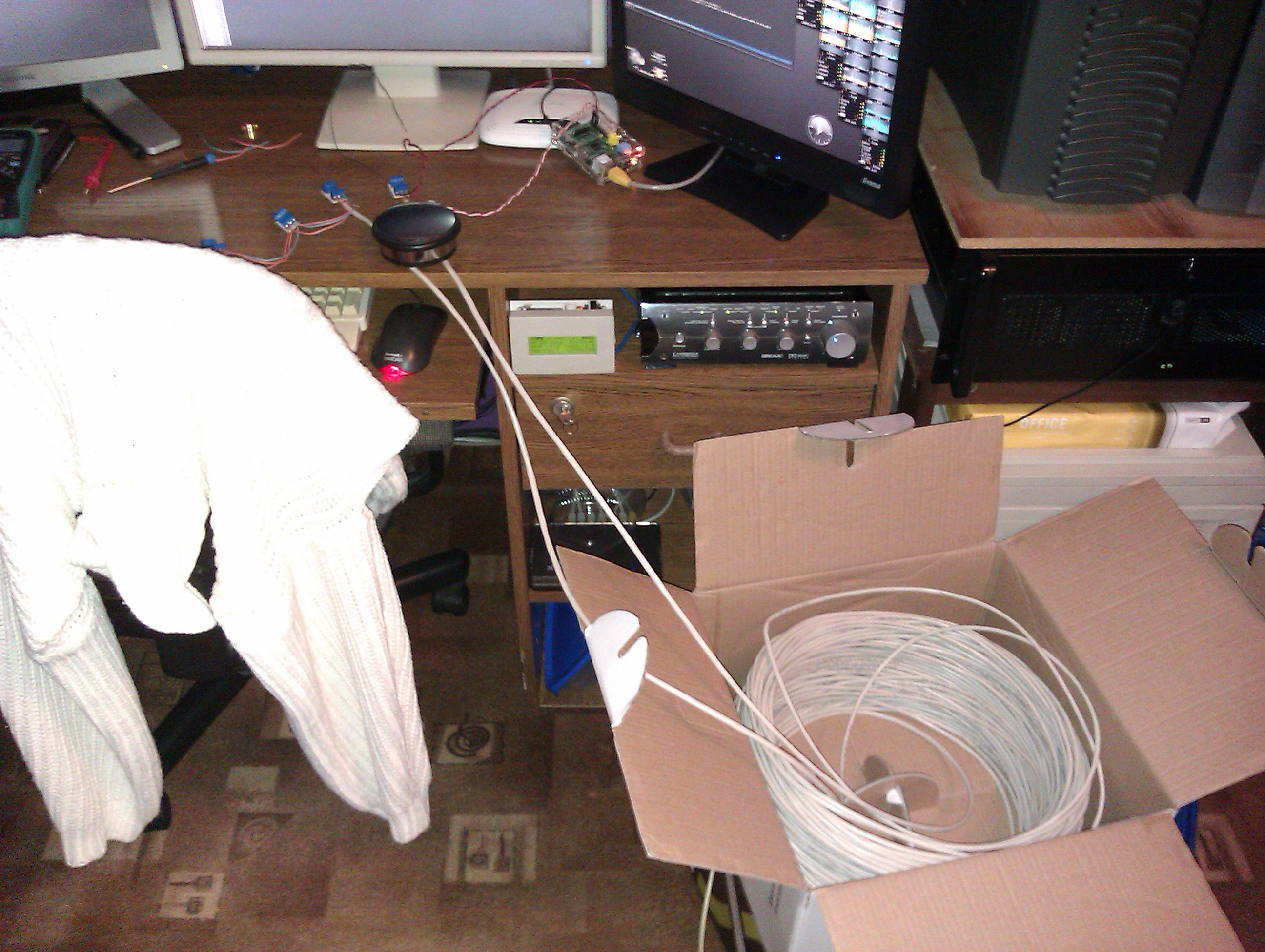
When I bought my brand new Raspberry Pi in 2012 (model B, version 2.0 with 512MB of RAM), then I needed a stable 1-wire bus for my home automation. Firstly I was testing it with w1-gpio kernel module which is emulating a 1-wire bus master using a bit-bangling (software) method:

As a result I had a plenty of errors when communicating with slave devices. Then I connected it with additional 101 meters of cable at the beginning of the bus:

The result was even worse: with 8 slaves I had about 1/3 communication errors, while with 22 sensors all of them was returning 0xFF as a read values.
I also have to note that the CPU usage using this bit-bangling method was high.

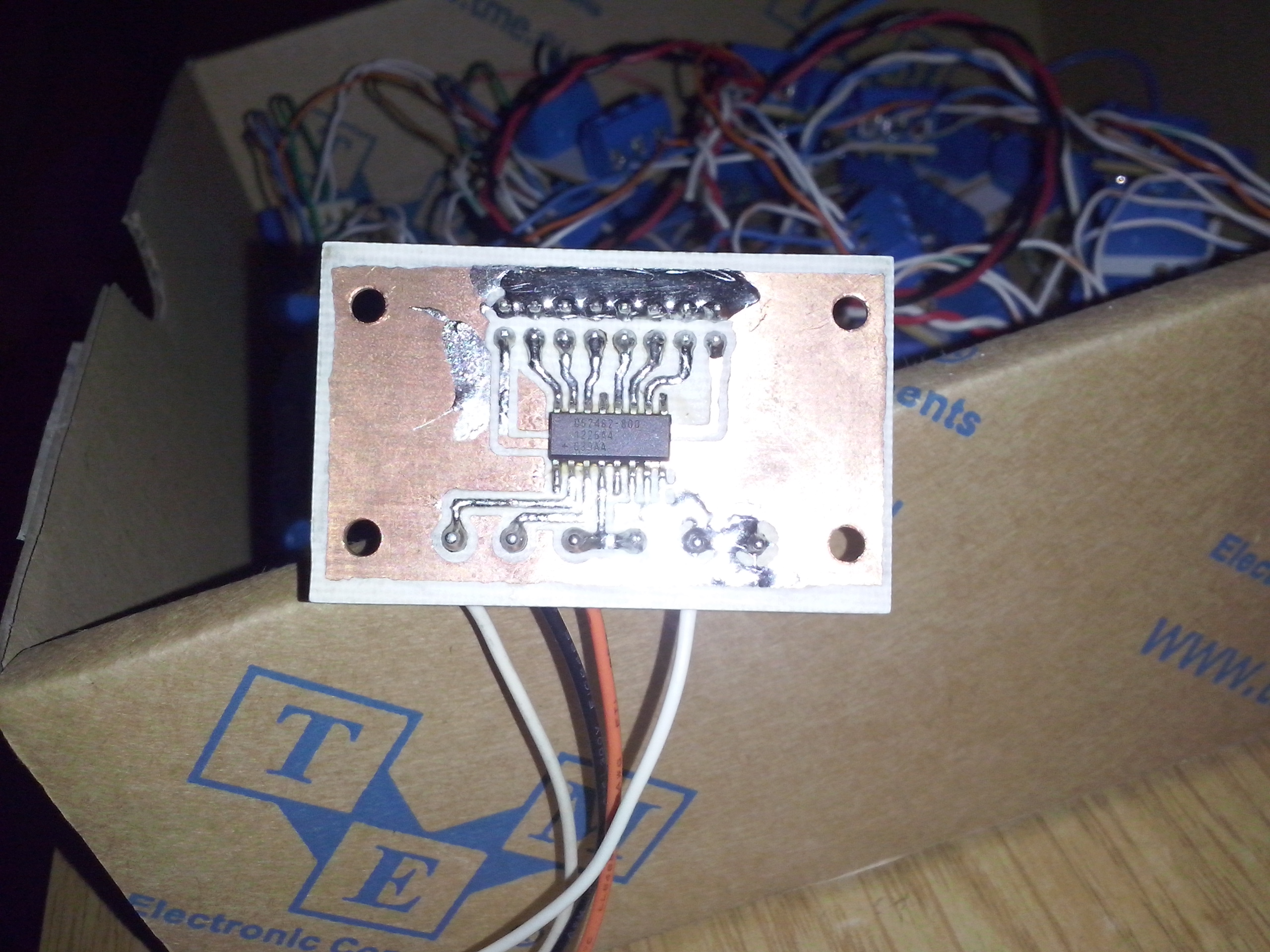
Using dedicated 8 channel 1-Wire master (DS2482-800)


The previous results shown that bit bangling method is not bad but only for several slaves and short connections.
The Raspberry Pi has a hardware i2c bus – and this was what I was looking for, so my next step was testing dedicated i2c <-> 1-Wire bus master chip. I ordered the DS2482-800 and created a PCB with 8 buses:

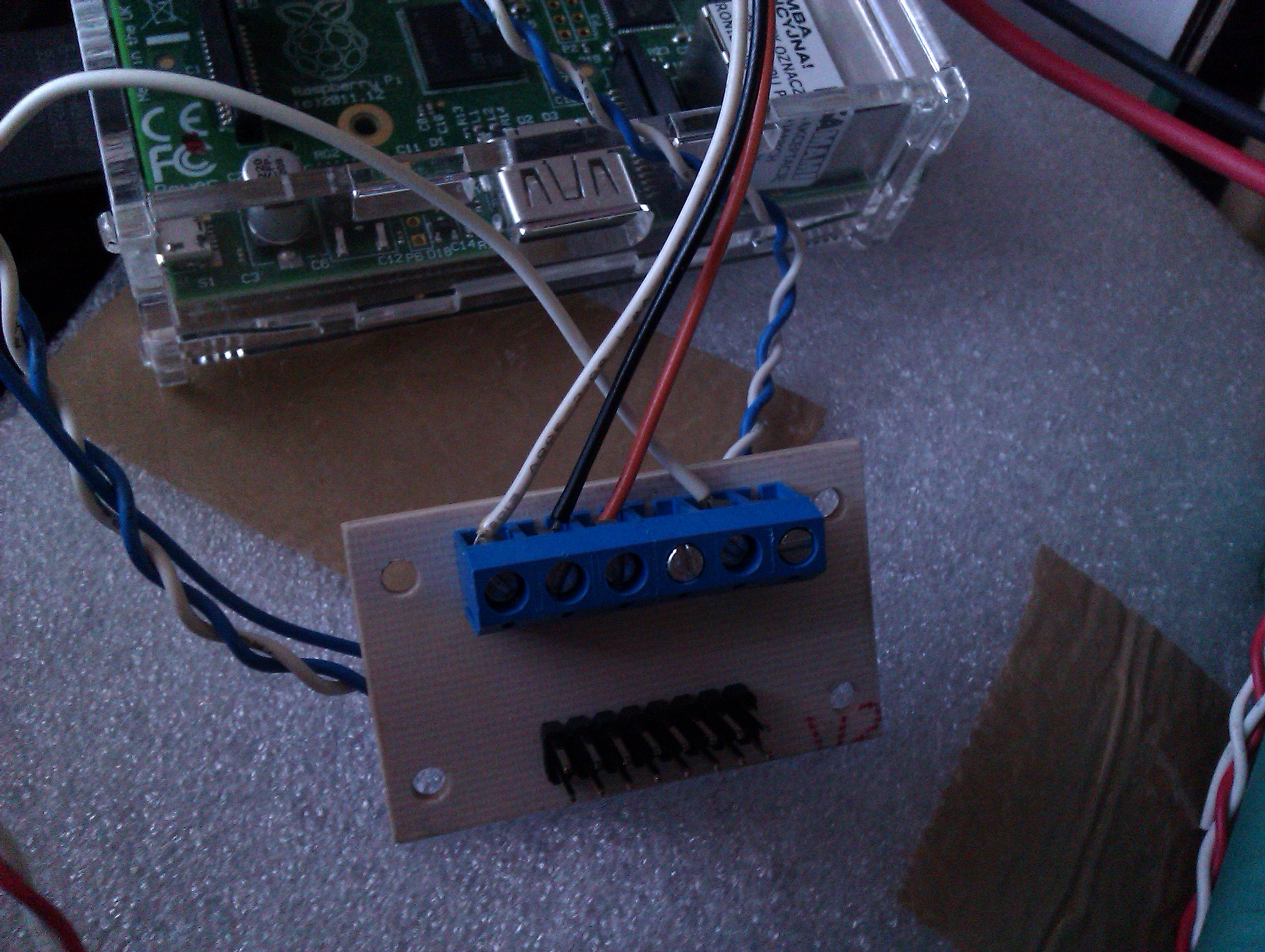
Connecting to the Raspberry Pi was as easy as connecting those four pins:

DS2482-800 Raspberry Pi GPIO header
VCC Pin 1 (3.3V)
SDA Pin 3 (SDA)
SCL Pin 5 (SCL)
GND Pin 9 (GND)

Before I connected it to the RPi, I unloaded the w1-gpio and typed:

modprobe i2c-bcm2708

as a result kernel dmesg shows this:

[ 27.431490] bcm2708_i2c bcm2708_i2c.0: BSC0 Controller at 0x20205000 (irq 79)
[ 27.556912] bcm2708_i2c bcm2708_i2c.1: BSC1 Controller at 0x20804000 (irq 79)
[ 44.040315] i2c /dev entries driver

Important: read also this article.

To be sure I detected devices on i2c:

root@raspberrypi:~# i2cdetect -y 1
     0  1  2  3  4  5  6  7  8  9  a  b  c  d  e  f
00:          -- -- -- -- -- -- -- -- -- -- -- -- --
10: -- -- -- -- -- -- -- -- -- -- -- -- -- -- -- --
20: -- -- -- -- -- -- -- -- -- -- -- -- -- -- -- --
30: -- -- -- -- -- -- -- -- -- -- -- -- -- -- -- --
40: -- -- -- -- -- -- -- -- -- -- -- -- -- -- -- --
50: -- -- -- -- -- -- -- -- -- -- -- -- -- -- -- --
60: -- -- -- -- -- -- -- -- -- -- -- -- -- -- -- --
70: -- -- -- -- -- -- -- --

Correct – no device so far. Then I connected the DS2482-800 and redo the detection:

root@raspberrypi:~# i2cdetect -y 1
     0  1  2  3  4  5  6  7  8  9  a  b  c  d  e  f
00:          -- -- -- -- -- -- -- -- -- -- -- -- --
10: -- -- -- -- -- -- -- -- 18 -- -- -- -- -- -- --
20: -- -- -- -- -- -- -- -- -- -- -- -- -- -- -- --
30: -- -- -- -- -- -- -- -- -- -- -- -- -- -- -- --
40: -- -- -- -- -- -- -- -- -- -- -- -- -- -- -- --
50: -- -- -- -- -- -- -- -- -- -- -- -- -- -- -- --
60: -- -- -- -- -- -- -- -- -- -- -- -- -- -- -- --
70: -- -- -- -- -- -- -- --

Great – a device on 0x18 address. Now I was ready to load the ds2482 module with:

modprobe ds2482

then I had to associate i2c device with this module typing:

echo ds2482 0x18 > /sys/bus/i2c/devices/i2c-1/new_device

and in dmesg I’ve got:

[ 1260.473311] i2c i2c-1: new_device: Instantiated device ds2482 at 0x18

As a result I’ve got 8 bus masters at:
/sys/bus/w1/devices/w1_bus_masterX, where X is the bus number

To be able to use more slave devices I had to modprobe the wire module with max_slave_count parameter, like this:

modprobe wire max_slave_count=30

After I have the bus master working I did a test with two buses connected to the master using short cables:

The result was great – the CPU usage was nearly zero and no communication errors.
It was a time to check this using longer cables: I connected several cables with a total length of 45.2m and 22 slave devices (mixed in the middle and also at the end of the bus):

Results? None of communication errors! All was working really stable even with this bus length 🙂

After all slaves on buses are detected, then it’s also worth (when you have static configuration) to disable scanning for new devices. It was locking communication with my slave devices on regular intervals and searching for new devices. I’ve disabled searching with the following commands:

echo 0 > /sys/bus/w1/devices/w1_bus_master1/w1_master_search
echo 0 > /sys/bus/w1/devices/w1_bus_master2/w1_master_search
echo 0 > /sys/bus/w1/devices/w1_bus_master3/w1_master_search
echo 0 > /sys/bus/w1/devices/w1_bus_master4/w1_master_search
echo 0 > /sys/bus/w1/devices/w1_bus_master5/w1_master_search
echo 0 > /sys/bus/w1/devices/w1_bus_master6/w1_master_search
echo 0 > /sys/bus/w1/devices/w1_bus_master7/w1_master_search
echo 0 > /sys/bus/w1/devices/w1_bus_master8/w1_master_search

Conclusions

Maybe the conclusion was obvious to you – but for the record:
If you are playing with 1-wire and use it for small amount of slave devices and with short length – a w1-gpio module and bit-bangling should be sufficient. If you will be using it with lengthy buses (maybe even more then single one) and more slave devices – better use a dedicated DS2482 i2c bus master for this 🙂

Comments

  1. Hi,
    Thank you very much. I did not know about the searching for new slave devices. I will try it out on my network.

    You have been using the bus-master with 3.3v. Is this sufficient even over long distances? I have been using i2c bridges to connect my 3.3v ALIX to 5v DS2482 system. If you have made good experiences, I will switch to 3.3v too.

    Thanks. BR

    1. Hi,
      I currently have in my production system several buses starting from one point (bus master) and going to different places of the whole house.
      So a single bus is roughly up to 20 meters long. On each bus I have several DS2413’s, DS1820’s and sometimes DS2408 or DS2438.
      The bus master (DS2482) is powered only from my Raspberry Pi 3.3V power pin and I am not noticing any problems with it (besides some garbage/crc errors on the 1wire bus when some noisy tools/motors are powered; but this is rare, and I believe it is caused because I wrongly installed the buses – parallel to the power cables).
      As I pointed in the article, the longest bus I’ve tested, was 45m (this was on my development desk, not in real home-environment).

      Just curious: And you? How long bus(es) have connected to the DS2482? 🙂

  2. Hi, article helped me a lot. One point i didn’t got. How can 1 map the “w1_bus_masterX” to the DS2482-800 chip if i use more than one ??? is the I2C Address “order” the sequence ???

    I want to find out how i can find the “Line” where a specific 1 Wire Device is connected to.

    greetings georg

    1. Hi!
      If you use more then one DS2482 chip then you need to adjust the i2c address to not conflict with the rest you are using on i2c. Look in the datasheet:
      https://www.maximintegrated.com/en/products/interface/controllers-expanders/DS2482-800.html
      “Three Address Inputs for I2C Address Assignment”

      And regarding the 1wire bus: Every w1_bus_masterX is probably the sequence number registered by the chip driver in the kernel. I am not using more then single chip so I am not sure, but I assume that if you’d add the second one with command:
      echo ds2482 0xXX > /sys/bus/i2c/devices/i2c-1/new_device
      then It would probably add another 8 buses:
      w1_bus_master9 .. w1_bus_master16

      Every 1wire slave device is associated with the bus it belongs to. Don’t worry about it – the kernel is doing its work automatically even by creating a symlinks, ie:
      /sys/bus/w1/devices # ls -la
      total 0
      drwxr-xr-x 2 root 0 0 Oct 24 19:09 .
      drwxr-xr-x 4 root 0 0 Oct 24 19:09 ..
      lrwxrwxrwx 1 root 0 0 Oct 24 19:10 10-0008003be0fa -> ../../../devices/w1_bus_master7/10-0008003be0fa
      lrwxrwxrwx 1 root 0 0 Oct 24 19:10 10-0008006b3991 -> ../../../devices/w1_bus_master7/10-0008006b3991
      lrwxrwxrwx 1 root 0 0 Oct 24 19:11 26-0000020d2650 -> ../../../devices/w1_bus_master4/26-0000020d2650
      lrwxrwxrwx 1 root 0 0 Oct 24 19:10 28-000000bbcfb7 -> ../../../devices/w1_bus_master4/28-000000bbcfb7
      lrwxrwxrwx 1 root 0 0 Oct 24 19:10 28-0000019b51e4 -> ../../../devices/w1_bus_master1/28-0000019b51e4

      1. thanx

        address bit’s of the chip i know but now i can calculate
        first echo ds2482 gave master 1..8 and second echo gave 9..16 and this is not depending to the I2c Address
        and the line of the chip is visible by the “name” e.g. below: /w1_bus_master4/*
        lrwxrwxrwx 1 root root 0 Nov 6 18:13 28-0316559efdff -> ../../../devices/w1_bus_master5/28-0316559efdff
        lrwxrwxrwx 1 root root 0 Nov 6 18:13 28-031661e8ccff -> ../../../devices/w1_bus_master4/28-031661e8ccff
        lrwxrwxrwx 1 root root 0 Nov 6 18:10 w1_bus_master1 -> ../../../devices/w1_bus_master1
        lrwxrwxrwx 1 root root 0 Nov 6 18:13 w1_bus_master2 -> ../../../devices/w1_bus_master2
        lrwxrwxrwx 1 root root 0 Nov 6 18:13 w1_bus_master3 -> ../../../devices/w1_bus_master3
        lrwxrwxrwx 1 root root 0 Nov 6 18:13 w1_bus_master4 -> ../../../devices/w1_bus_master4
        lrwxrwxrwx 1 root root 0 Nov 6 18:13 w1_bus_master5 -> ../../../devices/w1_bus_master5
        lrwxrwxrwx 1 root root 0 Nov 6 18:13 w1_bus_master6 -> ../../../devices/w1_bus_master6
        lrwxrwxrwx 1 root root 0 Nov 6 18:13 w1_bus_master7 -> ../../../devices/w1_bus_master7
        lrwxrwxrwx 1 root root 0 Nov 6 18:13 w1_bus_master8 -> ../../../devices/w1_bus_master8
        lrwxrwxrwx 1 root root 0 Nov 6 18:13 w1_bus_master9 -> ../../../devices/w1_bus_master9

  3. Hi, great job. I got a question what python library are you using if any for taking the temp from 1 wire slaves in this configuration? I believe the original w1thermsensor won’t work due to different path for slave devices.

    Thanks in advance
    Pawel

    1. Hi munal,
      I am not using any python script. I am keeping the slave device addresses and configuration in sqlite database and reading the devices in C code.

      regards

      1. Hi manio,
        Thanks for explanation, ok so I will tune a bit the path in the available library and that should work 🙂 Will update on the results. Thanks

  4. Hi,
    Thanks for sharing your knowledge.

    I am just attempting to switch over from “bit banging” to DS2482-800 controller for greater capacity. I have loaded an RPi 2B with fresh install of Stretch and have gotten to the point of this command “echo ds2482 0x18 > /sys/bus/i2c/devices/i2c-1/new_device” where I get permission denied. I have placed sudo at start of command as I am logged in as pi but still have permission denied.

    Any suggestions?
    cheers
    Geoff

  5. Hi,

    thank you for sharing your knowledge.

    I read your article and decided to begin a project with two ds2482-800 for a total of 16 buses (ideally I would need about 9-10).
    So I bought two chips. Having very little soldering knowledge, I used two SOP16 to DIP16 like these https://it.aliexpress.com/item/10Pcs-SOP16-SSOP16-TSSOP16-To-DIP16-0-65-1-27mm-IC-Adapter-PCB-Board-top/32572329898.html?spm=a2g0s.9042311.0.0.u6ng88 and a prototyping breadboard. I want to connect some ds18b20 spread over my house.

    After some minutes of testing, the second of my ds2482-800 (addressed 0x19) stopped working. A reset does not solve the problem, and when I try to instantiate it, I get the following error:
    # echo ds2482 0x19 > /sys/bus/i2c/devices/i2c-1/new_device
    Jan 14 15:46:16 raspberrypi kernel: [ 171.954786] ds2482 1-0019: DS2482 reset status 0x10 – not a DS2482

    I had a look in the device driver code, and found it looks for a reset status of 0x18, which means Device Reset and Logic Level high.
    I made some tests with i2cget and i2cset and I found I have two channels, 0 and 4 (corresponding to w1_bus_master1 and w1_bus_master5 in Linux), which give Logic Level 0 upon reset of the device, hence a status of 0x10 and not 0x18.

    The other channels are OK, but incidentally the driver tests the channel 0 upon device activation. Notably, the two faulty channels are the ones close to the GND pin.

    Thinking about having a falty chip, I bought other two, tried them and after some minutes of testing, I had the same issue.
    If I use them in position 0x18, the problem persists.

    Randomly, sometimes they get newly “alive”, work for some minutes, then the errors on the 0 and 4 buses return, and I know that they are newly gone: I get read errors in the 2 faluty channels, the other channels still work, but when I reboot the system, I can not instantiate the chip withe the usual error “DS2482 reset status 0x10 – not a DS2482”. In the meantime, before rebooting, I get errors like these:

    Jan 14 15:37:05 raspberrypi kernel: [ 212.898058] w1_master_driver w1_bus_master1: w1_search: max_slave_count 64 reached, will continue next search.
    Jan 14 15:40:17 raspberrypi kernel: [ 405.386298] w1_master_driver w1_bus_master5: Family 0 for 00.c00000000000.ca is not registered.
    Jan 14 15:40:34 raspberrypi kernel: [ 421.762533] w1_master_driver w1_bus_master1: Family 0 for 00.60000064140a.57 is not registered.
    Jan 14 15:41:49 raspberrypi kernel: [ 497.059989] w1_master_driver w1_bus_master1: Family 0 for 00.e0000064140a.db is not registered.
    Jan 14 15:42:01 raspberrypi kernel: [ 508.896594] w1_master_driver w1_bus_master5: Family 0 for 00.200000000000.23 is not registered.

    # ls -l /sys/bus/w1/devices/
    total 0
    lrwxrwxrwx 1 root root 0 Jan 14 15:38 00-20000064140a -> ../../../devices/w1_bus_master1/00-20000064140a
    lrwxrwxrwx 1 root root 0 Jan 14 15:39 00-400000000000 -> ../../../devices/w1_bus_master5/00-400000000000
    lrwxrwxrwx 1 root root 0 Jan 14 15:36 00-800000000000 -> ../../../devices/w1_bus_master5/00-800000000000
    lrwxrwxrwx 1 root root 0 Jan 14 15:39 00-a0000064140a -> ../../../devices/w1_bus_master1/00-a0000064140a
    lrwxrwxrwx 1 root root 0 Jan 14 15:34 28-314d2e126461 -> ../../../devices/w1_bus_master3/28-314d2e126461
    lrwxrwxrwx 1 root root 0 Jan 14 15:34 w1_bus_master1 -> ../../../devices/w1_bus_master1
    lrwxrwxrwx 1 root root 0 Jan 14 15:34 w1_bus_master2 -> ../../../devices/w1_bus_master2
    lrwxrwxrwx 1 root root 0 Jan 14 15:34 w1_bus_master3 -> ../../../devices/w1_bus_master3
    lrwxrwxrwx 1 root root 0 Jan 14 15:34 w1_bus_master4 -> ../../../devices/w1_bus_master4
    lrwxrwxrwx 1 root root 0 Jan 14 15:34 w1_bus_master5 -> ../../../devices/w1_bus_master5
    lrwxrwxrwx 1 root root 0 Jan 14 15:34 w1_bus_master6 -> ../../../devices/w1_bus_master6
    lrwxrwxrwx 1 root root 0 Jan 14 15:34 w1_bus_master7 -> ../../../devices/w1_bus_master7
    lrwxrwxrwx 1 root root 0 Jan 14 15:34 w1_bus_master8 -> ../../../devices/w1_bus_master8

    The w1_bus_master3/28-314d2e126461 is a real ds18b20, the other 00-* fake devices on w1_bus_master1 and w1_bus_master5 are all the result of errors.
    I don’t know what to look for. I may have failed soldering a chip, but I think not three, yelding exactly the same problem.

    Maybe you may have some idea on what I could think about?

    For reference, I do not use parasite power on my buses; initially, I put 4.7k pullups on my buses, then removed them because from what I understand from the specs, the ds2482 should have internal pullups.

    Thank you
    Luigi

    1. Hi Luigi,
      I have it similar as you: no parasite power of DS18B20 (I am even using 3.3V for power from bus and 5V for powering my DS18B20), no pull-ups (yes, DS2482 is doing it for you and moreover it can provide a strong pull-up).
      Unfortunately I didn’t have similar problems as you (using single DS2482-800).

      I don’t know if it will help you but you can at look at my tips which just comes to my mind:
      1. Check your schematic, soldering and all pin contacts, check whether the ground is properly connected.
      2. Check your power supply – try to change it if you can – maybe it is not efficient enough? RPi is very sensitive to power supply.
      3. Try to use only one chip instead of using two DS2482 simultaneously.
      4. Try to disconnect all 1wire buses when you are doing tests (if you haven’t do so).
      5. You may also try as the last resort adjust the delays in ds2482 module driver and/or in 1wire module(s).

      1. Hi manio,

        thank you for the hints. I tried powering only one ds2482-800 alone by the rPI 3.3v. The situation is clearly improved. Some errors are still there, but they are rare compared to the previou situation. Now I’ll try adding other components and I’ll keep you updated here.
        Just one silly question, you tell that you separately power the ds18b20’s. You have connected the grounds, right?

        Thanks again,
        Luigi

        1. That’s good news 🙂
          I am also powering the DS2482-800 from my RPi’s 3.3V. And the DS18B20’s 5V is from the same power line as my main RPi power, so I don’t even need to connect the GND separately – I am just using Raspberry’s GND and it is sufficient and working ok. If you are using separate power supply, then of course, you need to connect the grounds together.

        2. Hi manio and all other readers,

          at the end I had a bunch of failing chips. I substituted them, and the problem is gone.
          Thank you again for the hints on the project!

  6. Hey,
    I have loaded ds2482 module for my master and connected one ds18b20 to bus.0. I can see the ds18b20 serial number and when I read the temperature from sysfs then it is returning 85000 which is definitely wrong. Then I have unloaded ds2482 and loaded owfs. When I read temperature from ds18b20 through owfs it is returning plausible values. Have you any idea why reading through ds2482 module is not working?

    1. Hi Pirmin,
      Sorry for delay (holidays). Do you have it connected the same using the kernel module and owfs? Is the DS18B20 connected with parasite mode or you are providing Vcc?

      1. I have the same problem here. My DS18B20 is powered with Vcc 3v.

        85000 apparently means it did not see a response from the sensor, but it comes back very quickly. Sometimes it takes longer and gets some other number, but so far these numbers do not seem to correspond to degrees C.

        I’ve had more luck with gpio bit banging so far. 🙁

  7. Hello everyone,
    first of all thank you for this very informative description,
    I use a rpi 3b + and a DS2482-800 for DS18B20 probes.
    I installed OWFS and it works fine in localhost.
    I am calling on you because I am new to programming.
    to make my raspberry pi as a PLC,
    I use a commercial software “CODESYS”, which reads the information contained in the file:
    / Sys / devices / w1_bus_master1 /.
    how to transfer the information created by owfs to this folder?
    Thank you for your help

  8. Hi,
    I wold like to share my experience, maybe you can point to mistake made by me. I am powering DS2482 from Pi 3V3 and 10 pieces of DS18B20s on several buses from Pi 5v supply, all have common GND, everything was working fine (several months till now). But yesterday I noticed that Pi is not working. After checking I found out that 3V3 supply reads 0 V which means that Pi’s PMIC is burned. I have to buy new Pi (I was using 3 B+) now. But I am not sure that the next Pi will not be burned. So could someone point to my mistake? Why was PMIC on my Pi burned? What I have configured wrongly?

    1. Hi Alex,
      I have Raspberry Pi Model B Rev 2. I am powering the Pi and slave devices on 1 wire buses with 5V power supply. DS2482-800 is powered from Pi’s 3.3V pin so the 1wire data is also 3.3V. So far the same configuration as yours. It is working fine for me for years.

      Are you sure the problem was not eg some shorts or surges?

      1. Hi,
        thanks for your reply. I have read on Pi’s homepage, that they are using a specially for Pi developed PMIC on Rev 3 B+, maybe it is not completely tested yet?? Anyway I’ll continue to observe if the problem comes again. Now I am going to power ds2482-800 from external power supply with DC-DC converter (to get constant 3V3) and slave devices also from external over DC-DC converter (5V) in order not to give Pi’s PMIC exclusively for Pi.

  9. If you ever think about turning this into a raspberry pi hat, you can use this device tree overlay programmed into the hat’s eeprom:
    https://gist.github.com/Kodest/9690cde2ebdd527bc7d40a325ba9e3de
    I have just tested this, and works very nice. The effect is that you don’t have to execute the following line:

    echo ds2482 0x18 > /sys/bus/i2c/devices/i2c-1/new_device

    And your w1 master comes up at boot instantly.

  10. Hi. I just did a clean install with a DS2482. Had trouble getting it recognized and producing the results in /sys/bus/w1/devices. Uname -a =Linux RPi3 5.10.17-v7+ #1403 SMP Mon Feb 22 11:29:51 GMT 2021 armv7l GNU/Linux. Added ds2482 to /etc/modules and used sudo bash => echo ds2482 0x18 > /sys/bus/i2c/devices/i2c-1/new_device and folders for all the bus masters and 1-wire devices appeared in /sys/bus/w1/devices, but on reboot they were absent. So I tried sudo crontab -e and added @reboot echo ds2482 0x18 > /sys/bus/i2c/devices/i2c-1/new_device and it appears to have worked with the folders for the bus masters and 1 wire devices being present. It may be a kludge but seems to get the result.

Leave a Reply

Your email address will not be published. Required fields are marked *