Monitoring Voltronic Power Axpert MEX inverter under Linux

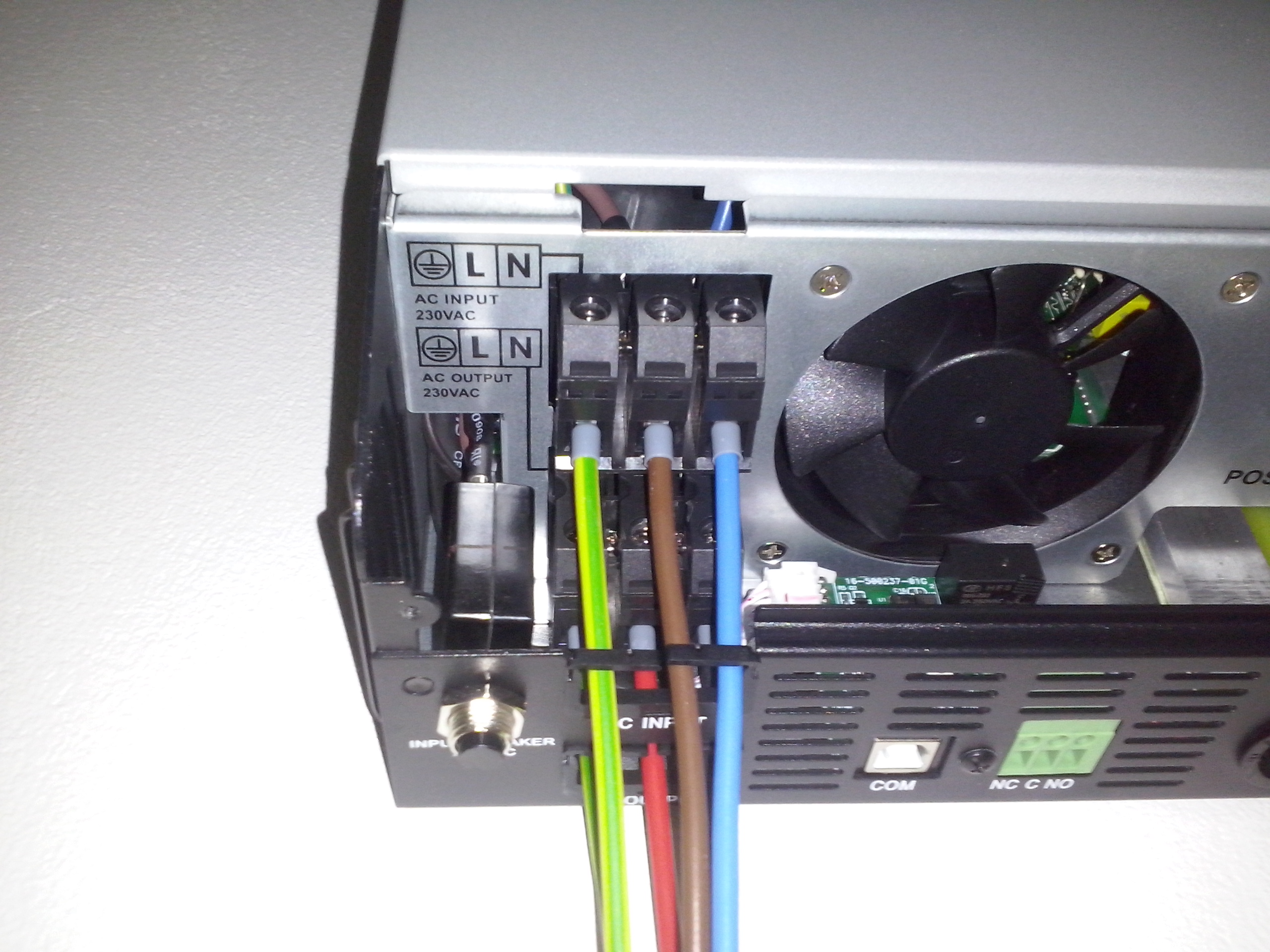
I am using the SKYMAX Expert MEX 3K-24 inverter. In fact it is identical with Voltronic Power Axpert MEX 3K-24, it was just rebranded by a Polish company.

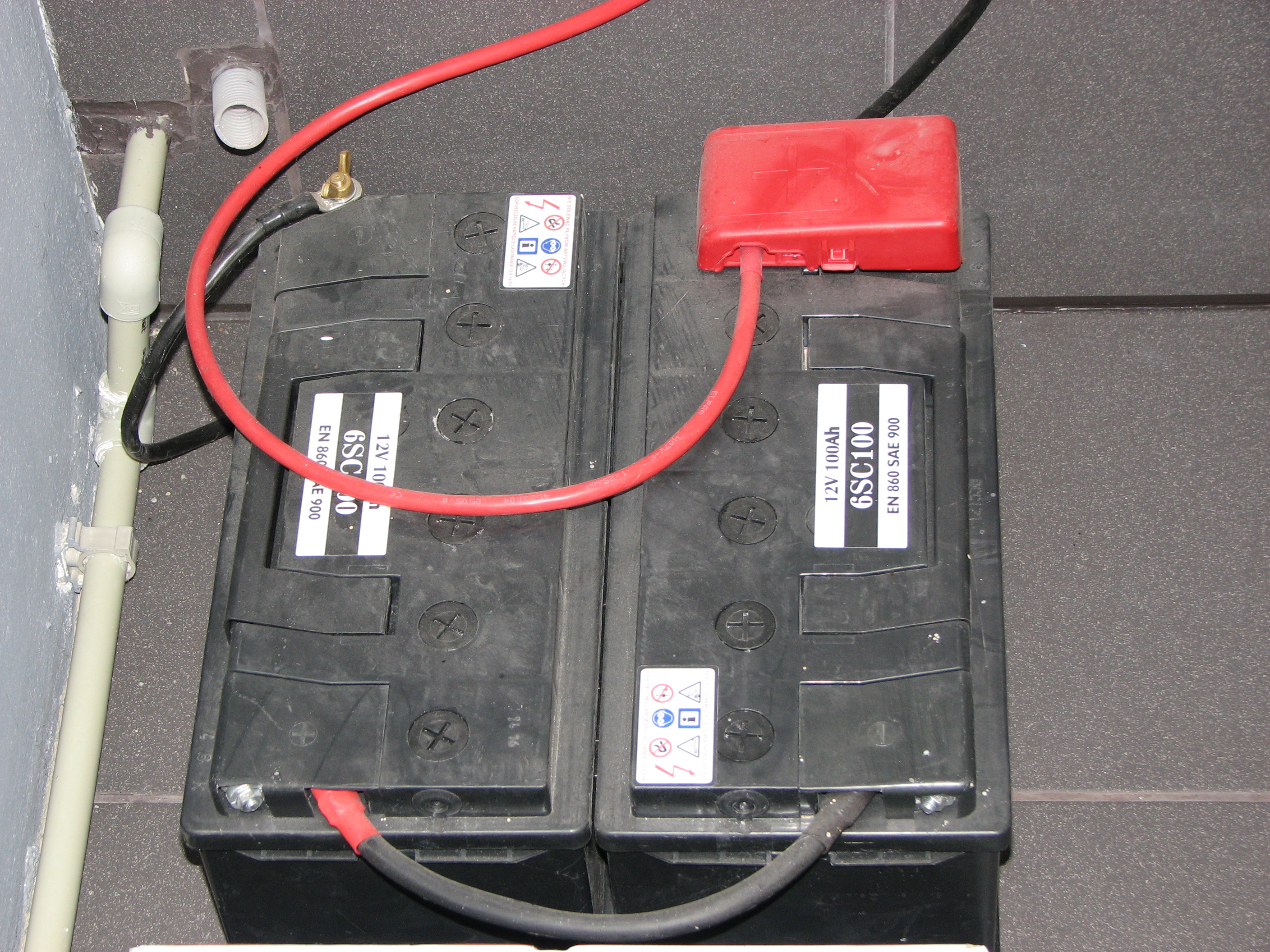
It is a 24 volts model, so I am using a two 12V 100Ah batteries connected in series (lead-acid automotive batteries):

I hope it will work longer then the batteries for APC 1400VA UPS, which I had before (and had to buy and replace batteries very often).
The model is not a hybrid one, which I’d love to have but for my purposes it is working really great so far.
The inverter has an integrated USB connector, so there is a way to communicate with the device.

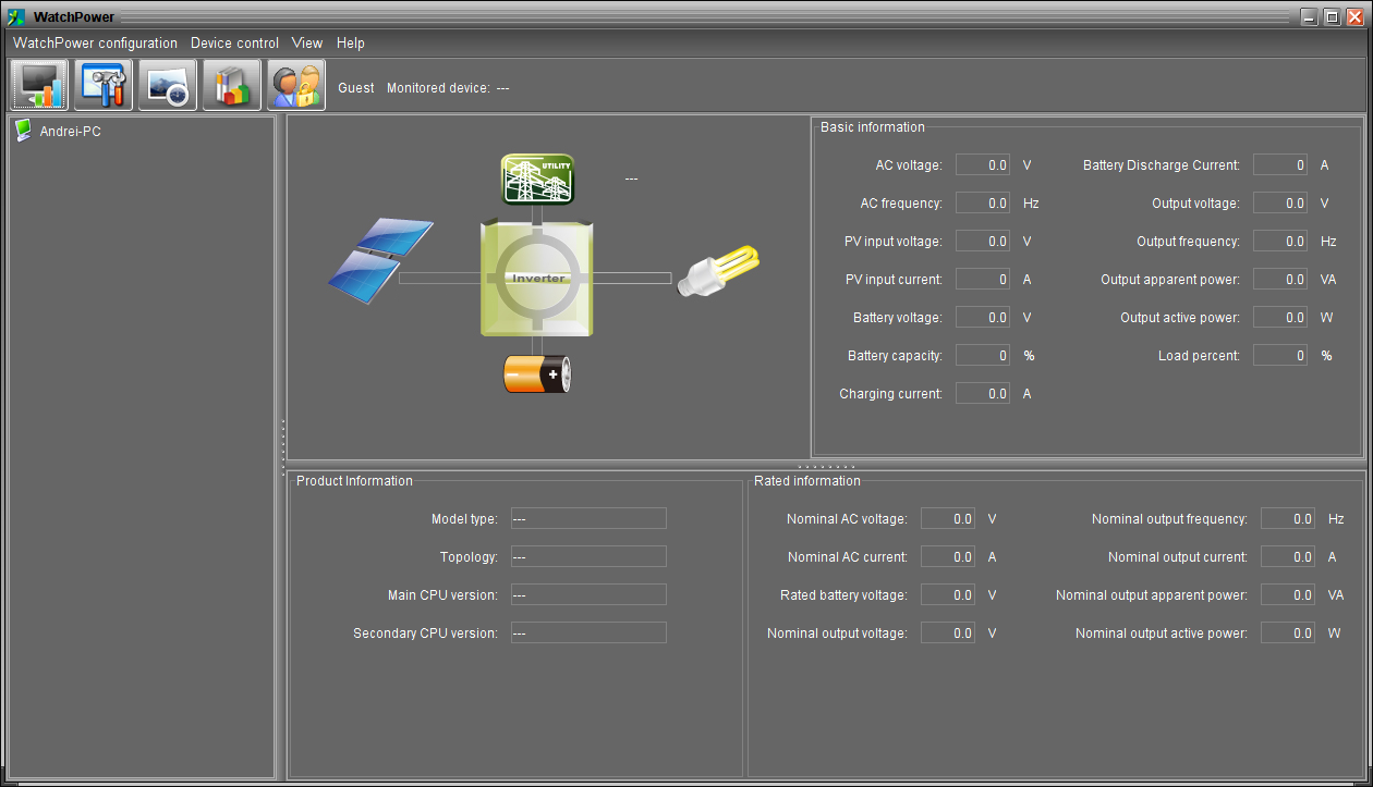
There is some creepy monitoring software called WatchPower, which is moreover written in Java:

There is even also a console version of the management software which can be run on Linux, but it also need Java (JRE) ๐Ÿ˜ฎ
Monitoring the inverter with this software on Raspberry Pi would be painful, so it was a time to discover how to do it the proper way ๐Ÿ˜‰

After plugging the USB to the Raspberry I’ve got in dmesg:

 [  523.116132] usb 1-2: new low-speed USB device number 2 using uhci_hcd
 [  523.329148] usb 1-2: New USB device found, idVendor=0665, idProduct=5161
 [  523.329160] usb 1-2: New USB device strings: Mfr=3, Product=1, SerialNumber=0

 [  525.073328] hidraw: raw HID events driver (C) Jiri Kosina
 [  525.111176] usbcore: registered new interface driver usbhid
 [  525.111184] usbhid: USB HID core driver
 [  525.213484] hid-generic 0003:0665:5161.0001: hiddev0,hidraw0: USB HID v1.11 Device [HID 0665:5161] on usb-0000:00:1d.0-2/input0

So it is a HID device visible in lsusb as:

Bus 001 Device 002: ID 0665:5161 Cypress Semiconductor USB to Serial

I sniffed with wireshark how the original program is talking to the device and I see that it is some pseudo-ASCII protocol.
The commands generally starts with Q letter, ie: QPI, QSID, QPIRI, QDI, QPIGS and the responses started with the ‘(‘ mark, and the results like this:

(230.1 49.9 230.1 49.9 0529 0483 020 393 27.03 000 100 0040 0000 000.0 00.00 00000 00010101 00 00 00000 110

At the end of the line is a two-byte CRC and new line character.

I’ve entered some of the command into Google to get some information about this protocol.
I have found great Australian and New Zealand forums with much information about the protocol and the hardware (maybe it’s more common at those markets). The most valuable for me was these two threads:
infinisolar 3k Plus realtime values and logging
PIP-4048MS and PIP-5048MS inverters

Based on this information I was able to integrate the support for the inverter in my Raspberry Pi.
There is no HID driver for the inverter, so I just used a generic device file: /dev/hidraw0.

In fact the most interesting commands for my constant monitoring was:
QPIGS – status (input, output voltages, currents, load, etc.)
QMOD – current mode (power-on, standby, line mode, battery mode, etc.)

So now instead of using the bloated Java software, I am just using simple and pure C code for monitoring the inverter on my RPi.
I created a sample demo project on github, so you can have a look or test how to query the inverter:
https://github.com/manio/skymax-demo

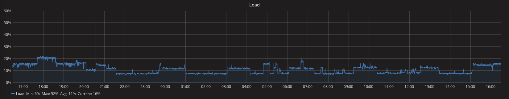
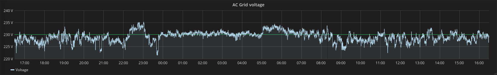
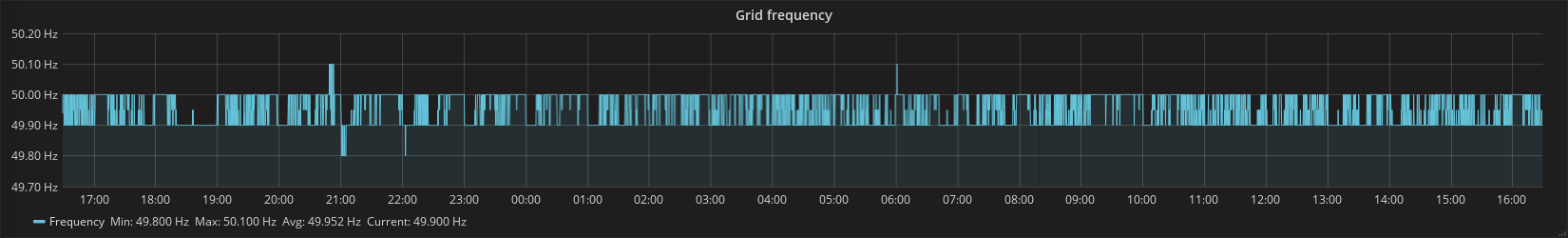
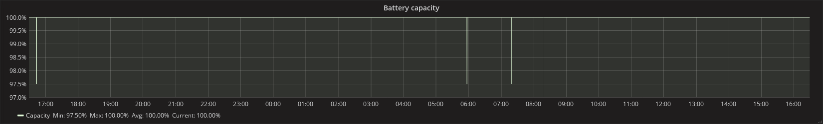
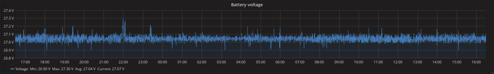
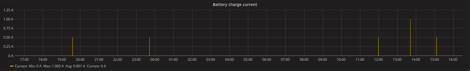
As usual I am providing some sample grafana plots, which I like very much in contrast to original software ๐Ÿ˜‰

Comments

  1. Hi. Would you be willing to put this in github? I’m looking to do a similar project and I’d prefer to build on something rather than reinventing the wheel. Thanks, Daryl

    1. Hi Daryl, I have it integrated in a larger home automation project which I am not willing to make public for several reasons. Anyway – I could try to make some small “demo” project which is using this skymax class and put it to the github. Is that ok to you?

      Update: I just pushed a sample code to the gihub, article is updated. Thanks! ๐Ÿ™‚

  2. Hi,
    I wonder if you could help. On my Raspberry Pi, it seems like the USB device reconnects every now and then, and a new device number being assigned to it. This results in your code stopping working after some time.

    Apr 30 21:36:11 raspberrypi kernel: [105134.832478] usb 1-1.2: USB disconnect, device number 12
    Apr 30 21:36:12 raspberrypi kernel: [105135.090308] usb 1-1.2: new low-speed USB device number 13 using dwc_otg
    Apr 30 21:36:12 raspberrypi kernel: [105135.233364] usb 1-1.2: New USB device found, idVendor=0665, idProduct=5161
    Apr 30 21:36:12 raspberrypi kernel: [105135.233387] usb 1-1.2: New USB device strings: Mfr=3, Product=1, SerialNumber=0
    Apr 30 21:36:12 raspberrypi kernel: [105135.262741] hid-generic 0003:0665:5161.000A: hiddev0,hidraw0: USB HID v1.11 Device [HID 0665:5161] on usb-3f980000.usb-1.2/input0

    pi@raspberrypi:~/skymax-demo/out $ ./skymax
    Sun Apr 30 21:55:55 2017 MAIN LOOP
    Sun Apr 30 21:55:55 2017 Unable to open device file (errno=13 Permission denied)
    ^C
    pi@raspberrypi:~/skymax-demo/out $ ll /dev/skymax
    lrwxrwxrwx 1 root root 12 Apr 30 11:43 /dev/skymax -> /dev/hidraw0
    pi@raspberrypi:~/skymax-demo/out $ ll /dev/hidraw0
    crw——- 1 root root 247, 0 Apr 30 21:36 /dev/hidraw0
    pi@raspberrypi:~/skymax-demo/out $ ls -lha /dev/hidraw0
    crw——- 1 root root 247, 0 Apr 30 21:36 /dev/hidraw0
    pi@raspberrypi:~/skymax-demo/out $ dmesg | grep hidraw
    [ 4.851059] hidraw: raw HID events driver (C) Jiri Kosina
    [ 6.063636] hid-generic 0003:0665:5161.0001: hiddev0,hidraw0: USB HID v1.11 Device [HID 0665:5161] on usb-3f980000.usb-1.4/input0
    [38893.331337] hid-generic 0003:0665:5161.0002: hiddev0,hidraw0: USB HID v1.11 Device [HID 0665:5161] on usb-3f980000.usb-1.4/input0
    [39134.255937] hid-generic 0003:0665:5161.0003: hiddev0,hidraw0: USB HID v1.11 Device [HID 0665:5161] on usb-3f980000.usb-1.4/input0
    [67552.001148] hid-generic 0003:0665:5161.0004: hiddev0,hidraw0: USB HID v1.11 Device [HID 0665:5161] on usb-3f980000.usb-1.2/input0
    [68779.180311] hid-generic 0003:0665:5161.0005: hiddev0,hidraw0: USB HID v1.11 Device [HID 0665:5161] on usb-3f980000.usb-1.2/input0
    [80602.567898] hid-generic 0003:0665:5161.0006: hiddev0,hidraw0: USB HID v1.11 Device [HID 0665:5161] on usb-3f980000.usb-1.2/input0
    [88754.726696] hid-generic 0003:0665:5161.0007: hiddev0,hidraw0: USB HID v1.11 Device [HID 0665:5161] on usb-3f980000.usb-1.2/input0
    [88814.625493] hid-generic 0003:0665:5161.0008: hiddev0,hidraw0: USB HID v1.11 Device [HID 0665:5161] on usb-3f980000.usb-1.2/input0
    [95764.943032] hid-generic 0003:0665:5161.0009: hiddev0,hidraw0: USB HID v1.11 Device [HID 0665:5161] on usb-3f980000.usb-1.2/input0
    [105135.262741] hid-generic 0003:0665:5161.000A: hiddev0,hidraw0: USB HID v1.11 Device [HID 0665:5161] on usb-3f980000.usb-1.2/input0

    1. Hi Rudi,
      I am using a 7.5m long USB A/B cable from the inverter to the Raspberry. First it was connected directly to the RPi, now I am using a powered USB hub. In both cases I have some transmission errors from time to time (I think it may be because of cable length), but I never had problems with disconnecting USB device – like you have currently. This kind of problem sometimes happens on my remote serial converter (also long cable), but it is rare.
      One way or another my point is that I’d just try to stabilize it somehow – maybe you could try to change the cable, connect it via USB hub, play with some kernel USB parameters…?
      Or even try to raise the power voltage. I had problems using other USB device without USB hub: when I raised the RPi power voltage by 100mV (from 5.0V to 5.1V) – then it was working more stable.
      Of course you can try to fix it in software, trying to detect such problems, but I’d rather fix it in hardware first. You can also try to connect it to the laptop/PC to check if the same problem exists…

  3. Good day Manio

    Do you know if it is possible to use an Arduino to log data from this inverter onto an SD card?
    We have a 5 kVA version of this inverter, which has a serial RS232 output.
    I will be able to connect the Arduino to the serial port through something like a MAX232 chip. I’m just not sure how I will receive and interpret the data from the inverter. Do you have any information available that will help?
    Also, do these inverters constantly send out a data stream through the serial/usb ports or do you need to request information before it is sent?
    Any information will be very helpful.
    Regards

    1. Hi Egon,
      If the RS232 protocol is similar/same, then it should be easy to do it. Of course I assume you know how to log the data to SD card :).
      As you can see in my article, I’ve created a sample demo application. The mentioned protocol is a query-response based, so answering your question: you need to request specific information and the inverter is then responding back.

      1. For anyone that’s stumbled across this article on the web – you can use RS232 also, just symlink the device to /dev/skymax like the USB example…

        I.e:

        ln -s /dev/ttyS0 /dev/skymax

  4. Hi there, i use a inverter pip 2424 from mpp solar i know it works similar . I was able to access the pcx60 charger via rs232 using a small pyhton script and send the datas to emoncms.

    The pcs60 was easy to access with raspberry pi and integrated functions. Bt thepip i connect va USB I am not able yet to access with the pi. Could you short descripe how you create that “/dev/hidraw0” ,

    is it possible open the divice same as an seriell device eg /ttyAMA0 ?

    Thanks for your help ๐Ÿ™‚

    1. Hi! There was no need to create the /dev/hidraw device. All HID devices that are detected by kernel (no matter if they are handled by dedicated kernel modules or not) are also available using the HIDRAW API:
      https://www.kernel.org/doc/Documentation/hid/hidraw.txt

      If there is a loaded kernel module for the specific HID device, then the device can be handled using additional device files (depending on module). But in this case there is no such module available, so the only way to communicate with the inverter was using the hidraw device.

      And answering your question: No, without the driver there is no serial emulation and no serial devices are available.

      ps. you have a nice dashboard ๐Ÿ˜‰

    2. I know this is a very old question but I got it to read my MPP pip2424lv by disabling the check for start/stop bytes and CRC in inverter.cpp. That’s as far as I’ve gone, I’m not a developer and I just wanted to read present values (then send to an MQTT server, but that’s separate). Thought I’d share what I couldn’t find online but discovered.

  5. Hi, I am getting
    Thu Mar 8 09:33:25 2007 MAIN LOOP
    Thu Mar 8 09:33:28 2007 Skymax: QPIGS read timeout
    Thu Mar 8 09:33:28 2007 Skymax: QPIGS reply too short (0 bytes)
    Thu Mar 8 09:33:31 2007 Skymax: QMOD read timeout
    Thu Mar 8 09:33:31 2007 Skymax: QMOD reply too short (0 bytes)

    How can I sort this problem out? I created a symbolic link to /dev/ttyS0 (RS232 communication) and how can I get this to graph to grafana?

    1. Hi Raymond,
      I don’t know what hardware you are using, but the sample code was tested on the USB-HID inverters (eg. via a /dev/hidraw0 device file). You are passing a regular serial port /dev/ttyS0 instead of the USB one. I did not tested it over a serial port. I am not even sure if it us using the same protocol. The best thing for you would be if you can sniff the serial communication when using official software and compare the commands…

      Regarding grafana: It is too big topic to response here in the reply. You just need to create some script which is passing the values from the inverter to the graph storage you are using. If you are not using grafana currently, then there are plenty of tutorials how to install and using it. Google is your friend here ๐Ÿ™‚

      Some basics are eg here:
      https://www.digitalocean.com/community/tutorials/an-introduction-to-tracking-statistics-with-graphite-statsd-and-collectd
      https://lkhill.com/using-influxdb-grafana-to-display-network-statistics/

  6. Hello. I am working with the Voltronic Infini 10K hybrid solar inverter. According to several posts all over the internet the communication interface on the USB side and the RS-232 side should be the same or at least very similar to the device you are using. I fetched your code from github and adapted it so that it would just query the protocol id (QPI) and the device id (QID). Whatever command I am sending to the hidraw device I always get exactly eight Bytes back (0x 5e 30 1b e3 0d 00 00 00). Also quite often I get errno 32 (broken pipe) when trying to write to the device. The open command executes successfully.

    I am not quite clear on how the interface to the hidraw device works. I was under the impression, that USB expects very specific frames (reports) of data in which the payload is embedded. And that there is a specific procedure to initiate the USB device before it may be used through some special control reports. Could you point me in the right direction on this? Any help is greatly appreciated.

    Sincerely,
    Freddy

    1. Hi Freddy,
      To be honest I don’t know what the response means. In ASCII it looks like:
      “^0”. I assume you don’t have a valid responses also for the QPI or QID commands…
      I just don’t bother about USB HID protocol “reports” – it is an upper layer which the kernel is doing itself. I am just only opening the hidraw device and writing the commands directly (with it’s checksums). Then and I can read from the device to obtain the inverter response.
      If you have broken pipe, then it seems that there is something wrong with the hidraw device? USB cable problems? what is in your dmesg in this case?

      My tip for you: try to run official software eg. on some window laptop, run eg. wireshark in the same time and sniff what commands are passed to the inverter and how it is responding. It will be a good ground to start adapting the sample code…

    2. Hi Freddy,

      Did you ever come right with your 10KW inverter? I tried the code on an Infinisolar 5KW inverter, also made by Voltronics (and it also use the same SolarPower software) but get the following error:

      Thu Feb 1 11:14:06 2018 Skymax: QPIGS read timeout
      Thu Feb 1 11:14:06 2018 Skymax: QPIGS reply too short (8 bytes)
      Thu Feb 1 11:14:06 2018 Skymax: QMOD: incorrect start/stop bytes

      1. Hey guys,

        Not sure if you are still interested, but I have an MPP solar, MPI 5k – which I believe is a re-branded Infini 5K… These units, don’t use the same RS232 commands as the unit that Manio is using, I reverse engineered the java software and pulled out the protocol, below is a brief overview of what you can send it:
        Always starts with ^ – also note the ^0 you get, is some kind of NAK.
        xxx is the number of bytes in the command + the CR, so a command which is quite useful is GS, this would be send as ^P003GS\r
        battery status is BATS
        which would be ^P005BATS\r
        Also, it seems that each command is being sent 8 bytes at a time, I think it’s something to do with the USB protocol, so, I write to the stream (c# running on mono) then flush the buffer, then perform another write with the rest of the command.

        I’ve found data such as battery voltage, load amount, output frequencies, voltages, etc, doesn’t seem to be any actual power output which is a shame.

        But if you guys are interested in more info, flick me an email, murray dot porter at gmail dot com…

        1. Hi Murray ,

          You seem to be the only one that mentions the ^P00 protocol.
          I have a Infinisollar VII 3kv that uses that protocol.
          I sniffed some usb commands with Wireshark, but I am still evaluating what it means.
          I am using the ^P005ID ^P007PIR ^P005DI ^P005GSX commands to get data of the inverter, but I have not been able to send any configuraton changes (seem to be related to ^S006PDI and ^S006PEI commands) .
          The commands need to be sent in two parts ( ^P007PIR + ^Iรƒยฎ8.7PIR for example) to get a propper responce.
          I am using PYUSB to communicate directly to the HID.

          did you get anny further on this?
          regards,
          Darko

          1. Is this an mppsolar hybrid V 4K? it is difficult to operate this inverter P18

          2. Darko,

            sorry, I didn’t get an email saying I had responses… I’ve progressed quite a bit now, I’ve reverse engineered most the interesting bits, can get all the info I need as well as set settings. Drop me an email and I can give you some more detail as I don’t know if I’ll get a notification to this comment..

          3. Guys, I’ve put up a basic c# project on github search for MPSInverterPoller and you can download and give it a go, it uses the RS232 port for comms, you can cross-compile it to run on Raspberry PI with a single command. You can also just peruse the details in there and convert it to your own code if you like.

          4. Hi Darko

            I have the Infini Solar VIi 5KW and assume I need to communicate with it exactly the way you are.

            Please give more detail on how I send the commands in 2 parts. I have been connecting directly to ttyUSB0 using the screen command on the pi but I’m not getting any data back. My most successful reply was (Nkss and 0โ–ก.

            I think I’m close yet so far. Any
            help is greatly appreciated.

            Oh yes, Thanks Manio. This post really helped me

  7. I am quite curious, have you also noticed the bus voltage running at about 430V? Do you know what the “bus voltage” is? I can’t find much reference about it, other than “I is an Integer ranging from 0 to 9. The units is V.”

    1. No idea what the voltage is truly is. I am just logging it as it is passed by the inverter. In fact it is described as:
      “BUS voltage I is an Integer ranging from 0 to 9. The units is V.”, but the value is not integer from 0 to 9 but eg.: 393 ๐Ÿ™‚
      which is opposite to eg battery voltage, which is eg: 27.03.

  8. thank you very much for this great work
    my output is
    Skymax: QPIGS: 110 bytes read: (001.0 00.0 229.0 50.0 0000 0000 000 389 24.86 000 066 0497 0000 000.0 00.00 00001 10010000 06 04 00000 000
    Skymax: QMOD: 5 bytes read: (B
    AC Grid voltage: 1.0
    AC Grid frequency: 0.0
    AC out voltage: 229.0
    AC out frequency: 50.0
    Load [%]: 0
    Load [W]: 0
    Load [VA]: 0
    Bus voltage: 389
    Heatsink temperature: 497
    Battery capacity [%]: 66
    Battery voltage: 24.86
    Battery charge current [A]: 0
    Battery discharge current [A]: 1

    there still solar voltage,solar current & solar power
    if i can read them it would be a great help

    1. Hi Alawx,
      Sorry, I am not using solar in my case so even if I’ve got those values, I cannot test if it is properly parsed. Please just read the protocol documentation and try to discover the values yourself. Good luck! ๐Ÿ™‚

  9. Dear Manio,
    how would I have to modify your code, so I can send commands (e.g. to switch modes) while it is running? Open a TCP port and listen for some command? Please help…

    1. You need to be a programmer, and if you have such skills your question would not be a problem to solve. It is just up to you if you open TCP port or do it differently. You just need to write some daemon which is monitoring the inverter when idle, and in the same time it is listening for incoming commands (If I’ve got your intentions right).

  10. i see the name manio comming up is it the same manio from icc and centurion?
    Anyway heres my story (textwall warning)
    ive buyed 2 all-in-one inverters called outback SPC III and it included Watchpower as monitoring software. As it work in java i cant monitor and view both at the same time on one screen beside a go around with VMs so ive been looking for an easy setup for both to
    view the way i need (watchpower doesnt give that) . i encounter telegraf ,influxdb and grafana and it took me awhile to make it work together. on a testing laptop i got it working and i can see with everything localy running , the cpu of the laptop. The next step would be a plugin for telegraf to gatter modbus data and turn it in time series data for sending into influxdb. Here does my journey ends as im not a programmer and im a noob in these things.

    I use windows as OS (8.1 on laptop 10 on everything else .Linux is a big hassle to me as i did tryed it in the past and never got it working for me . For that im afraid to start on rasberry pie . im realy not gona start on those things , i feel im to old or to slow to start on these things and as my time is limited i cant take the time to learn.

    On search i found out that software around data is big business and my solar system costed me somuch that i cant pay for a decend monitoring software thats why opensource grafana was looking great for me untill now as i cant get pass the last bump.

    This bump is that Telegraf cant gatter modbus and converting it . there is no plugin for it..yet and i have no clue if there is one , how to get it in telegraf. alot gets pointed to github and in github you get some view of … i think a bunch of code and no explaination how or what todo with it.

    im an plug and play guy , i can struggle with settings in a try-and-error methode . it took me a month with the limited daytime to get the telegraf-influxdb-grafana-browser to work.

    what im asking is that the smart people here could try to create a working plugin for telegraf and with a noob prooved explaination todo so.

    i know 2 people did working on it (fdamador and garciaolias) but dunno if they still are.
    Its the only thing missing togo forward to get an dashboard adapted to my needs .

    i dont need 25 metrics in numbers , i dont need stats graphs , i need clean and big gauge with in the middle in big numbers how much watts my solar power give for each inverter and one combined so that i know when i can start my big loads like my washingmachine or dryer and also want to see the SoC of the batteries . thats it and i believe that grafana can show me this when modbus is included in telegraf.

    I wish we get an windows exe that installs the plugin into telegraf but with all the github thing i doubt to get it .

  11. Hello
    I have a question ?
    Why skymax shows no
    “PV_in_watts and PV_in_watthour”
    All other values are displayed correctly.
    Do you have an idea?
    Here is a small summary of the values:
    “Inverter_mode”: 4,
    “AC_grid_voltage”: 240.2,
    “AC_grid_frequency”: 50.0,
    “AC_out_voltage”: 229.0,
    “AC_out_frequency”: 49.9,
    “PV_in_voltage”: 167.0,
    “PV_in_current”: 18.0,
    “PV_in_watts”: 0.0,
    “PV_in_watthour”: 0.0000,
    “SCC_voltage”: 0.0000,
    “Load_pct”: 19,

    thank you in advance
    Sralus

    1. Sralus, you should post your questions as issues on the Github project page so that they can be logged and tracked by others if you have issues with the application, and are not just commenting on Manio’s original blog post …

      The PV functions is new code that was just added yesterday, intended to be used with a ‘daemon’ that runs every 30 seconds (see: https://github.com/ned-kelly/docker-voltronic-homeassistant) – For it to be accurate, you will need to execute the program every 30 seconds — If you want to ‘poll’ more frequently – you will need to modify the `run_interval` line in the inverter.conf.

      You could run the process every 30 seconds using the linux watch command … ie:
      watch -n 30 “inverter_poller -1” > /dev/null 2>&1

  12. Thanks @Manio for posting the code on github.
    Just let you guys know if you are getting invalid start/stop bits error, try using different cable. In my case I was using a usb extension cable.
    Please do share some insights on your home automation project sometime, it would be really interesting to read.
    Cheers

  13. Nice job! I knew someone must have looked into this after dealing with the Watchpower software. My goal is to use a RPI 3B+ as well, and have it powered via the batteries directly, and simply have the graphing work so I can see it remotely.

  14. Hi Manio,
    I have tried to compile your code on a raspberry pi 3B and I got some error. Can you please help with some hints on how to get over it?
    Here is the output of the console :

    pi@raspberrypi:~/skymax-demo $ cmake .. && make
    — The C compiler identification is GNU 8.3.0
    — The CXX compiler identification is GNU 8.3.0
    — Check for working C compiler: /usr/bin/cc
    — Check for working C compiler: /usr/bin/cc — works
    — Detecting C compiler ABI info
    — Detecting C compiler ABI info – done
    — Detecting C compile features
    — Detecting C compile features – done
    — Check for working CXX compiler: /usr/bin/c++
    — Check for working CXX compiler: /usr/bin/c++ — works
    — Detecting CXX compiler ABI info
    — Detecting CXX compiler ABI info – done
    — Detecting CXX compile features
    — Detecting CXX compile features – done
    — Configuring done
    CMake Error at CMakeLists.txt:7 (ADD_EXECUTABLE):
    No SOURCES given to target: inverter_poller

    — Build files have been written to: /home/pi/skymax-demo

  15. Hi Manio.
    I hope you can help. When I run inverter-poller the voltage stats/output looks wrong.
    ” sudo ./inverter_poller -1 -d
    Wed Oct 13 14:14:49 2021 INVERTER: Debug set
    Wed Oct 13 14:14:49 2021 INVERTER: Current CRC: 49 C1
    Wed Oct 13 14:14:49 2021 INVERTER: QMOD reply size (5 bytes)
    Wed Oct 13 14:14:49 2021 INVERTER: QMOD: 5 bytes read: (L
    Wed Oct 13 14:14:49 2021 INVERTER: QMOD query finished
    Wed Oct 13 14:14:49 2021 INVERTER: Current CRC: B7 A9
    Wed Oct 13 14:14:49 2021 INVERTER: QPIGS reply size (110 bytes)
    Wed Oct 13 14:14:49 2021 INVERTER: QPIGS: 110 bytes read: (232.2 49.9 232.2 49.9 0348 0289 011 406 26.90 020 095 0032 00.0 000.0 00.00 00000 00010101 00 00 00000 010
    Wed Oct 13 14:14:49 2021 INVERTER: QPIGS query finished
    INVERTER: ampfactor from config is 1.00
    INVERTER: wattfactor from config is 1.00
    {
    “Inverter_mode”:3,
    “AC_grid_voltage”:232.2,
    “AC_grid_frequency”:49.9,
    ….
    “Load_pct”:11,
    “Load_watt”:289,
    “Load_watthour”:9.6333,

    “Battery_recharge_voltage”:2507429599441968108794190078410752.0,
    “Battery_under_voltage”:2507497067174109162019172080680960.0,
    “Battery_bulk_voltage”:2505705148967243574071255598366720.0,
    “Battery_float_voltage”:2470574886532403052630168251138048.0,
    “Max_grid_charge_current”:1995915668,
    “Max_charge_current”:1995920204,
    “Out_source_priority”:1995915668,
    “Charger_source_priority”:1995913900,
    “Battery_redischarge_voltage”:165670047957801842896750675853389594624.0,
    “Warnings”:””
    }
    Wed Oct 13 14:14:50 2021 INVERTER: All queries complete, exiting loop.”

    I am using a usb connected from my Rpi to the inverter.

    1. Hello Adrian,
      Indeed the values looks really bad. I think the problem is that my code was prepared for my inverter and my specified firmware. I know that protocol may differ from model to model and even from firmware version to another version. For what it’s worth I can point you to some guys who seems are maintaining current code (my code was forked). So maybe you can start/ask for help there:
      https://github.com/ned-kelly/docker-voltronic-homeassistant/pull/53

  16. Hi Manio.
    I hope you can help.

    MPP Solar / Infinisolar MPI 10k hybrid inverter

    pi@raspberrypi:~/skymax-demo/build $ sudo ./inverter_poller -1 -d
    Thu Jun 2 11:13:12 2022 INVERTER: Debug set
    Thu Jun 2 11:13:12 2022 INVERTER: Current CRC: 49 C1
    Thu Jun 2 11:13:12 2022 INVERTER: QMOD reply size (5 bytes)
    configuration options for the actual inverter polling process…es. Buffer: ^0

    The device to read from…
    Use: /dev/ttyS0 if you have a serial device,
    /dev/ttyUSB0 if a USBSerial,
    /dev/hidraw0 if you’re connecting via the USB port on the inverter.

    device=/dev/hidraw0

    How many times per hour is the program going to run…
    This is used to calculate the PV & Load Watt Hours between runs…
    If unsure, leave as default – it will run every minute…

    (120 = every 30 seconds)…
    run_interval=120

    This allows you to modify the amperage in case the inverter is giving an incorrect
    reading compared to measurement tools. Normally this will remain ‘1’
    amperage_factor=1.0

    This allos you to modify the wattage in case the inverter is giving an incorrect
    reading compared to measurement tools. Normally this will remain ‘1’
    watt_factor=1.01

    Thu Jun 2 11:13:12 2022 INVERTER: Current CRC: B7 A9
    Thu Jun 2 11:13:15 2022 INVERTER: QPIGS read timeout
    Thu Jun 2 11:13:15 2022 INVERTER: QPIGS reply too short (8 bytes)
    Thu Jun 2 11:13:15 2022 INVERTER: Current CRC: F8 54
    Thu Jun 2 11:13:18 2022 INVERTER: QPIRI read timeout
    Thu Jun 2 11:13:18 2022 INVERTER: QPIRI reply too short (8 bytes)
    Thu Jun 2 11:13:18 2022 INVERTER: Current CRC: B4 DA
    Thu Jun 2 11:13:21 2022 INVERTER: QPIWS read timeout
    Thu Jun 2 11:13:21 2022 INVERTER: QPIWS reply too short (8 bytes)
    Thu Jun 2 11:13:26 2022 INVERTER: Current CRC: 49 C1
    Thu Jun 2 11:13:26 2022 INVERTER: QMOD reply size (5 bytes)
    โ–’hu Jun 2 11:13:26 2022 INVERTER: QMOD: incorrect start/stop bytes. Buffer: ^0
    Thu Jun 2 11:13:26 2022 INVERTER: Current CRC: B7 A9

    Thanks

  17. Hello ,
    it’s a great Job .
    I don t know if I should ask you this but ,
    I wonder if you can help me on monitoring Voltronic invertrer by snmp on zabbix.
    Stay well .

    1. I assume you’re talking about SNMP/ethernet card plugged in the inverter. This is a different story and I am sure you’ll easily find some guide on the internet how to monitor it in zabbix.

Leave a Reply to Guido Cancel reply

Your email address will not be published. Required fields are marked *